TECHNICAL INFORMATIONS OF WELD-ON PROFILES
WELD-ON PROFILES – IMPLEMENTATION

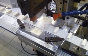
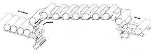
1 / Welding of profiles
The thermoplastic polyurethane, base of BRECO® welded (V) and BRECOFLEX® belts, can be used to produce profileed belts by means of a welding process.
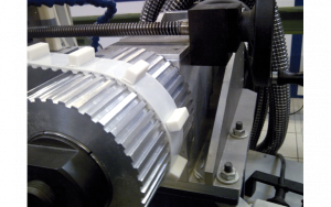
The profiles, depending on how many there are, are welded on manually or automatically.
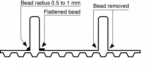
The welding bead is between 0.5 and 1 mm thick and with varying degrees of flattening.
If the welding bead were to obstruct your application, specify in the drawings or in the order “Bead removed”.
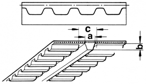
2 / Width of the weld
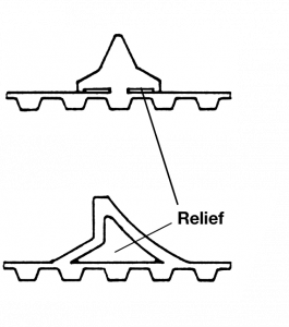
To maintain the flexibility of the belt as it wraps over the pulleys, the profiles are only welded on in their centre section with a support point on either side, or else at the two ends with a central relief.
 |
 |
 |
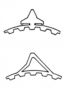
Profiles that require large weld surfaces can be made more flexible by means of slits. |
In the case of transversal profiles welded on high-width belts, it will be necessary to take into account possible “transversal bending” (consult us).
3 / Position and thickness of profiles
The flexibility of the timing belt can be altered by the position of the weld-on profile depending on whether it is aligned over a tooth or a tooth gap. The first option is the preferred solution.
As a general rule the thickness S of the profile must be as low as possible. The table below sets out the maximum profile thicknesses S based on the number of pulley teeth and the position of the profile in relation to the tooth.
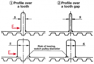
F : permissible nominal force at the profile base. 20 daN/cm2 on the weld section.
Thickness Smax as a function of number of pulley teeth and belt type(values established on the base of 92 Sh hardness profiles).
|
18 |
20 |
25 |
30 |
40 |
50 |
60 |
100 |
|||||||||
|
① |
② |
① |
② |
① |
② |
① |
② |
① |
② |
① |
② |
① |
② |
① |
② |
|
|
T2,5 |
3 |
2 |
3 |
2 |
3 |
2 |
4 |
2 |
5 |
3 |
5 |
4 |
6 |
6 |
||
|
AT3 |
3 |
2 |
4 |
2 |
5 |
3 |
6 |
3 |
8 |
4 |
9 |
6 |
10 |
8 |
||
|
T5 |
4 |
2 |
5 |
2 |
6 |
2 |
6 |
3 |
8 |
4 |
9 |
6 |
10 |
8 |
12 |
10 |
|
T10 |
7 |
3 |
8 |
3 |
9 |
4 |
10 |
4 |
12 |
6 |
14 |
9 |
15 |
12 |
20 |
20 |
|
T20 |
11 |
4 |
12 |
5 |
13 |
5 |
15 |
6 |
18 |
8 |
20 |
12 |
23 |
20 |
30 |
30 |
|
AT5 |
4 |
2 |
5 |
2 |
6 |
2 |
6 |
3 |
8 |
4 |
9 |
6 |
10 |
8 |
12 |
10 |
|
AT10 |
7 |
3 |
8 |
3 |
9 |
4 |
10 |
4 |
12 |
6 |
14 |
9 |
15 |
12 |
20 |
20 |
|
AT15 |
11 |
4 |
12 |
5 |
15 |
7 |
17 |
10 |
19 |
16 |
25 |
25 |
||||
|
SFAT10* |
6 |
7 |
8 |
9 |
10 |
12 |
14 |
20 |
||||||||
|
BATK10* |
6 |
7 |
8 |
9 |
10 |
12 |
14 |
20 |
||||||||
|
SFAT15* |
8 |
9 |
10 |
11 |
13 |
15 |
16 |
25 |
||||||||
|
AT20 |
11 |
4 |
12 |
5 |
13 |
5 |
15 |
6 |
18 |
8 |
20 |
12 |
23 |
20 |
30 |
30 |
|
SFAT20* |
10 |
11 |
12 |
13 |
15 |
18 |
20 |
20 |
||||||||
|
MXL |
2 |
1 |
2,5 |
1 |
2,5 |
1,5 |
3,5 |
1,5 |
4 |
2 |
4,5 |
3 |
5 |
5 |
||
|
XL |
4 |
2 |
5 |
2 |
6 |
2 |
6 |
3 |
8 |
4 |
9 |
6 |
10 |
8 |
12 |
10 |
|
L |
5 |
3 |
6 |
3 |
7 |
3 |
8 |
4 |
10 |
5 |
12 |
7 |
13 |
10 |
16 |
16 |
|
H |
7 |
4 |
8 |
4 |
9 |
5 |
10 |
6 |
12 |
7 |
14 |
10 |
15 |
12 |
20 |
20 |
|
XH |
12 |
4 |
13 |
5 |
14 |
5 |
15 |
6 |
18 |
8 |
20 |
12 |
23 |
20 |
30 |
30 |
* These belts have offset or curved teeth; the value of Smax is the same regardless of where the profile is welded on.
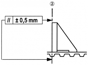
4 / Manufacturing tolerances
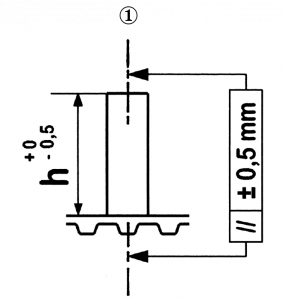
4.1 Positioning tolerance on the belt
The profiles are generally positioned in relation to a tooth.
The standard precision is ±0.5 mm between the axis of a tooth and the axis ① or the reference edge ② of a profile.
 |
 |
The width positioning tolerance is ± 0.5 mm in relation to the centre line of the belt or of an edge of the belt.
The profile height tolerance is 0 – 0.5 mm (note: the profile drawings are always dimensioned in the welded position).
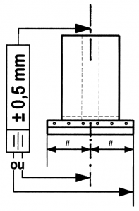
A profile supplied separately is therefore 0.4 to 0.7 mm higher to take into account the reduced height at the weld.
Closer tolerances can be obtained by means of additional machining or a specific welding process (consult us).
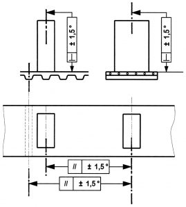
4.2 Perpendicularity and parallelism tolerances
The perpendicularity and parallelism tolerances are in the region of ±1.5°, like the tolerances for a different angle of 90°.
4.3 Positioning tolerance of profiles over the full length of a belt
Errors are not cumulative due to the fact that the profiles are positioned in relation to a tooth. However, it is necessary to take into account the belt length tolerance and possibly the elastic elongation under pre-tension force (Fpt).
If the profiles cannot be positioned in relation to a tooth, it is advisable to prepare a precise drawing and consult us.
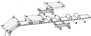
4.4 Tolerance of a group of profiles between themselves
Weld positioning equipment will be required when conveying and positioning necessitate a high degree of accuracy for a group of profiles. It is advisable to consult us with a precisely toleranced drawing.
Exemple :
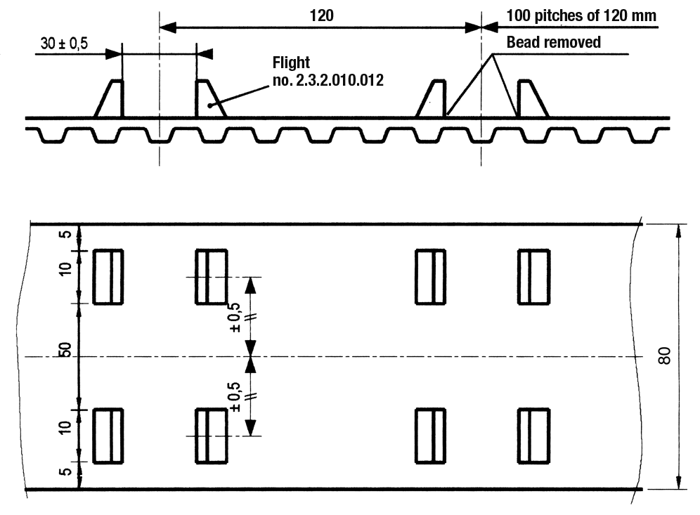
We will propose tolerances which we can guarantee based on our production options.
5 / Profiles
How weld-on profiles are produced is dependent on their number and their geometric complexity:
- Simple or complex high-volume profile: produced by moulding
- Simple low-volume profile: production by machining or water jet cutting from a polyurethane block.
It is also possible to produce moulded profiles on SYNCHROFLEX® belts. This procedure is the most reliable because it produces a high-strength profile/profile. However, it can only be used for large quantities because it requires investment in a complete mould.
We invite you to contact our sales department regarding our options before a new profile is created: we have in effect a library of more than 3000 different models and we regularly create new models in response to customer requests.
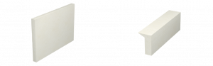
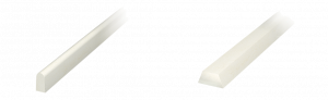
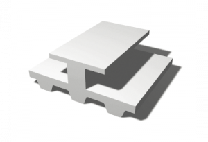
5.1 Extra-flat profiles
Profiles reinforced or not reinforced with glass fibre.
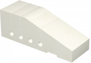
Application example: conveying cosmetic, hygiene and ultra-light products, diskettes.

5.2 Simple geometric profiles
Profiles can be offset for conveying.
Application example: light conveying on slider bed.
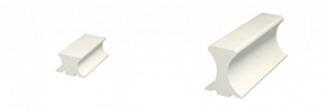
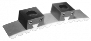
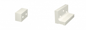
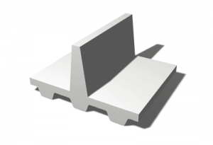
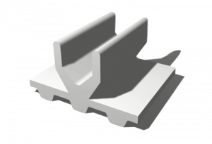
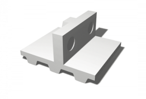
5.3 Support profiles
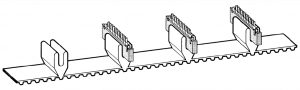
Profiles with geometry adapted to the parts to be conveyed.
Application example: conveying of connectors.

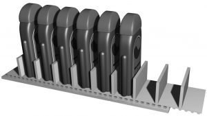
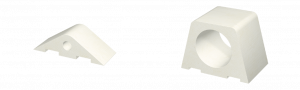
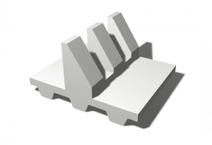
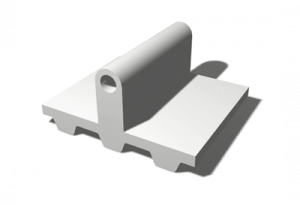
5.4 Gripping profiles
Profiles with a radius adapted to the cylinder to be conveyed.
Application example: gripping profile, held by gripping.
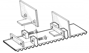
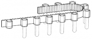
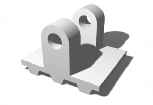
5.5 Profiles for shaft supports
Profiles accommodating shafts or bushings.
Application example: conveying with metal support.
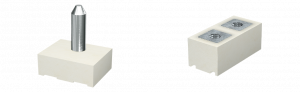
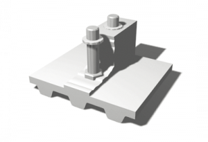
5.6 Profiles with inserts
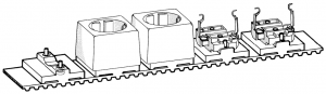
Smooth inserts for centring, threaded for fastening.
Application example: assembly of power sockets.
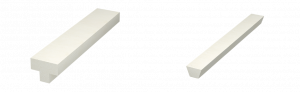
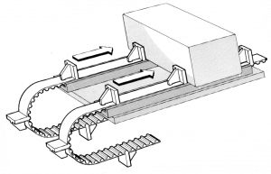
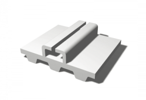
5.7 Longitudinal guide profiles
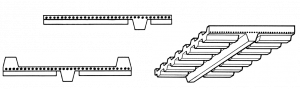
All the belts can be fitted with a longitudinal profile. The K6 and K13 profiles can essentially be attached to all belt types.
Application example: TK-ATK non-slit for guiding on grooved pulleys or profiled slider beds.
 |
Continuous trapezoidal profiles fastened by machining and welding: | ||
| K6 | K13 | ||
| a | 6 | 13 | |
| b | 4 | 16.5 | |
| c | 12 | 20 | |
Wrap diameter:
|
PITCH |
Number of teeth Z minimum |
Rollers on back minimum dia. in mm
|
|
TK5K6 |
25 |
60 |
|
ATK5K6 |
25 |
60 |
|
TK10K6 |
20 |
60 |
|
TK10K13 |
25 |
120 |
|
ATK10K6 |
20 |
120 |
|
ATK10K13 |
25 |
120 |
|
TK20K13 |
15 |
180 |
|
ATK20K13 |
25 |
180 |
|
HKk13 |
20 |
120 |
|
FK2K6 |
Ø 60 |
60 |
|
FK2K13 |
Ø 80 |
120 |
5.8 Profiles for assembly by insertion
Dovetailed or T profiles for mounting/removing specific dies.
Application example: rapidly interchangeable polyethylene dies.
5.9 Profiles with locating holes
Profiles for locating supplementary metal parts.
Application example: heavy conveying on polyamide slider beds.
5.10 Support profiles
Profiles with or without inserts, simple or with a large weld surface and flexibility slits.

5.11 Profiles specific to a function
We develop profiles adapted to your specific function.
Application example: profile designed to hold test tubes.

5.12 Clip-on profiles

Non-welded profiles.
Special models created for each application.

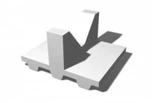
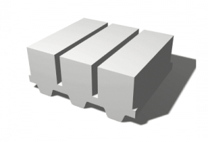
5.13 Some other examples
 |
 |
 |
 |
 |
 |
 |
 |
 |
 |
 |
 |
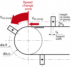
6 / Static and dynamic function of profiles for ATN belts
The characteristics of the insert parts are essential for determining the permissible forces on the drives. However, the design must take into account the dynamic forces which are produced in the acceleration phases and when the linear speed changes to peripheral speed on the pulley (Vlin to Vrot).
Our technical department can provide you with useful advice on determining the size of the profiles based on our curve sheets.

Timing belts or chains: 5 reasons to switch to timing belts
