TECHNICAL INFORMATIONS OF LINEAR APPLICATIONS
LINEAR APPLICATIONS
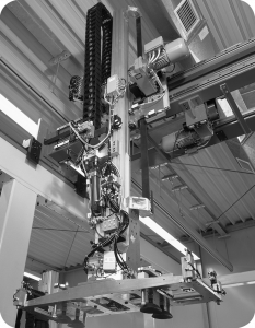
The term “linear application” is used to define the conversion of a rotational motion into a linear motion or the linear translational motion of an assembly (carriage, table…).
General design
• You are planning to effect simple travel without precision constraints
• Or, alternately, you are looking for precise positioning combined with high speeds, BINDER magnetic offers a full range of linear belts.
Our belts provide linear travel over short or/and long distances combining travel speed, positioning precision and repeatability.
In terms of design all the components of a transmission must have levels of mass and friction which are reduced as much as possible and the assembly must be designed to have optimum stiffness.
As a rule the ends of BRECO® linear AT and ATL timing belts and CONTI® Synchrodrive HTD timing belts are attached with clamp or tension plates.
The following pages set out the values of forces permissible by the teeth and the values of nominal forces transmittable by the reinforcement. Elements such as the transmittable forces and the constraints of stiffness can be different for an identical profile.
Example: AT and ATL10 belts have permissible forces for identical teeth, but the use of reinforced steel tension members in ATL belts lends the system better positioning precision, greater stiffness and better behaviour at the point of peak torque. This is also applicable to HTD belts, which can be manufactured with different tension members.
ATL belts are intended exclusively to provide linear motion, and therefore cannot be “joined”.
They can be used in a variety of applications:
• robotics,
• stackers,
• linear carriages…
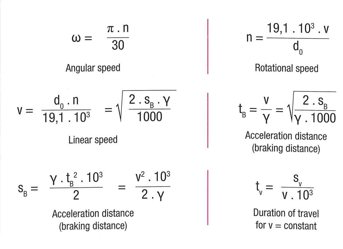
KINEMATICS
Linear drives are designed in accordance with three basic installations:
| Linear travel (motor at the end) | 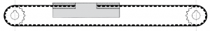 |
| Table translational motion (stationary intermediate motor) | 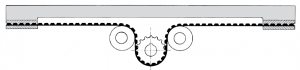 |
| Electric carriage (on-board motor) | 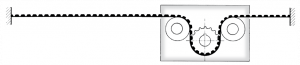 |
Symbols
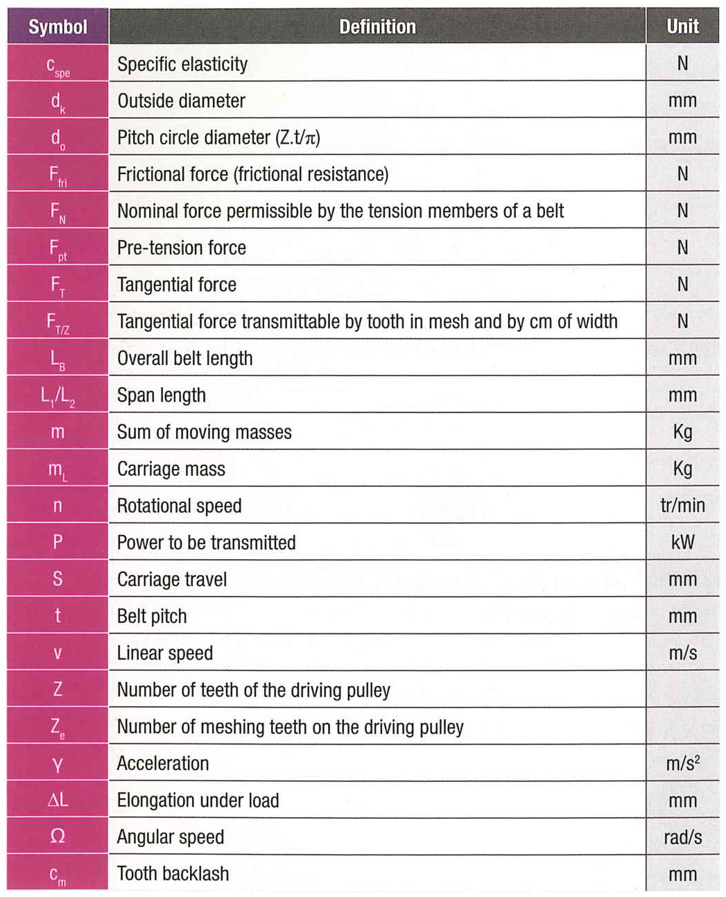
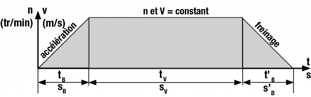
Diagram representing one operating cycle:
DETERMINATION OF A BELT
1 / Forces in the tension member
The tension members of belts are subjected to the following stresses:
Tangential force to be transmitted FT(N) comprising:
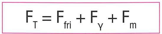
The frictional force Ffri(N)
The acceleration force Fγ(N) = Mass (kg) x Acceleration (m/s²)
Fm= Mass (kg) x 9,81 x β (where β angle of inclination of the belt in relation to the horizontal)
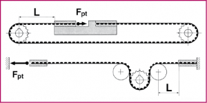
Pre-tension force Fpt (N) applied to the belt run during installation.
A linear drive is correctly pre-tensioned if, under the influence of the maximum tangential force FTmax, the slack span of the belt remains tensioned.
Under no circumstances should the “slack” span of the belt be slackened as this would causes teeth to jump on the driving pulley or other problems on the belt.
An optimum pre-tension force is therefore essential: see SM5.
 |
|
| These forces are to be added up to compare them with the limit values of force permissible by the tension members. | |
According to the application it will be necessary to take into account an additional higher or lower safety factor (consult us).
Note: the different mounting bearings will be selected to support the following forces:
F= 2xFpt + FT
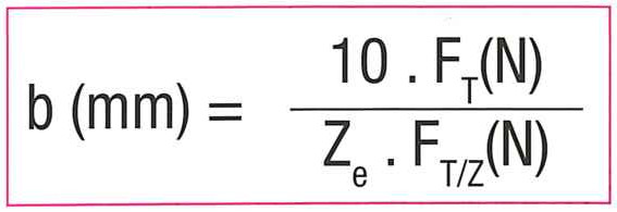
2 / Force transmittable by the teeth
Calculation of the belt width at nominal speed.
-Ze (max) for the calculation = 12 – above this it is deemed that the other teeth in mesh will no longer work. The number of teeth in mesh can moreover, according to the installation, be less than 12.
-FT/Z(N) must be determined with the diagram “Tangential force transmittable by the teeth” of the chosen pitch and profile.
Other formulae:
Precision and positioning
1 / Repeat accuracy
The repeat accuracy of a linear drive denotes its capacity to attain the same position under the same operating conditions.
This varies under the effect of the frictional force (Ffri) which is generated by a residual elongation when stationary.
We have:
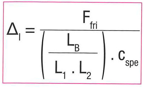
When the friction of the guiding system is negligible and the tooth backlash
cm = 0, the repeatability is in the order of +/- 0.05 mm.
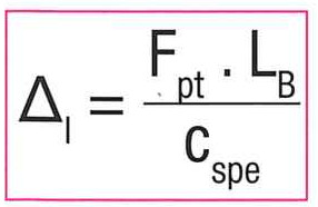
2 / Positioning precision
The positioning precision of a linear drive denotes its capacity to convert an angle of rotation of the drive pulley into a linear motion.
The actual linear translation depends on the applied forces and on the tolerances of all the subassemblies participating in the transmission motion.
2.1 Length tolerance and variation of the belt pitch
The length tolerance of the timing belt is rendered by a variation of the belt pitch. The length tolerance, in this case the pitch variation, depends on the belt extrusion tolerance and on the pre-tension force applied during installation. The belts are supplied with a length tolerance / pitch variation defined during production.
Corrective measures:
-Use BRECO® ATL timing belts, which have negative tolerances, enabling the nominal theoretical value during installation to be maintained.
-Consult our specialist technical advisers.
2.2 Circularity or concentricity of the driving pulley
These defects can cause a translation irregularity in a linear system which is rendered by a slight sinusoidal oscillation during travel.
Corrective measures:
-Verify the circularity and concentricity or if necessary reduce the tolerance range.
-Replace the key connection and use an expanding hub.
3 / Backlash on the reversal of direction
This depends in part on the functional backlash between the belt teeth and the tooth gap on the pulley, on the number of teeth in mesh and on the elongation of the belt in the wrap area.
In applications requiring a particularly high degree of transmission accuracy it is possible to use pulley tooth gaps with reduced (SE) or zero (0) backlash for certain pitches
Factors influencing meshing:
-Pre-tension
-Number of teeth in mesh (Ze)
-Loads (speed, dynamic performance…)
-Machining tolerances (of the pulley), extrusion tolerances, fitting tolerances.
4 / Stiffness / elongation of the belt
Linear transmissions are governed by Hooke’s Law relating to elastic deformation of steel.
4.1 Total elongation of the belt under pre-tension force
4.2 Elongation of the belt under the inertia of the displaced mass
The forces applied to a linear transmission induce variable elongations. The dynamic position deviation resulting from elongation can be calculated using the equation below; it is however necessary to take into account the stiffness of the whole drive assembly:
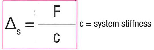
Linear systems demonstrate variable elasticities. Elastic behaviour thus depends on the ratio of lengths L1 and L2, from which the system stiffness “c” is obtained.
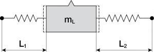
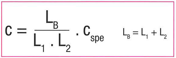
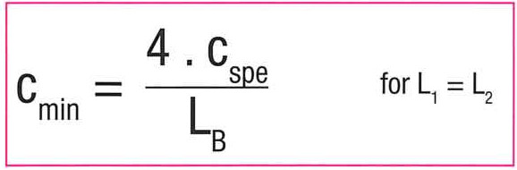
In other words, every position of the moving body demonstrates a particular elasticity “c”. This elasticity demonstrates a minimum value (cmin) when L1 and L2 are of the same length. In this case the value of cmin is:
5 / Natural frequency
Under the effect of a variation of force, a mass mL (the carriage) connected to a spring system (the belts) enters into oscillation damped to the natural frequency of the system.
The natural frequency of the system is:
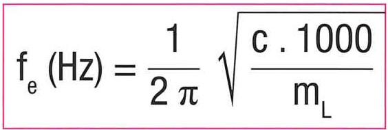
This formula does not take into account the masses of the pulleys and the belt (or others). It is also recommended to ensure that the frequency fe does not correspond to the frequency of the peak torques or to the meshing frequency.
Oscillation
Oscillation is the “back and forth” motion of the moving body (carriage or table) around a fixed point. Several kinds of oscillations can be envisaged according to the stiffness and the damping of the system. We strongly recommend the use of belts that have reinforced tension members (types ATL and HTD HP) to reduce the amplitude.

Timing belts or chains: 5 reasons to switch to timing belts
