TECHNICAL EXPLANATIONS OF BRAKES AND CLUTCHES
BRAKES AND CLUTCHES
DESCRIPTION AND OPERATION
– Brakes make it possible to stop a rotating shaft.
– Clutches are used to couple or uncouple a primary shaft to or from a secondary shaft.
Our brakes and clutches function only when dry in a protected ambient environment because the majority of these units have IP00.
The most important specification when choosing a brake is the torque in Nm. This torque can be defined as static or dynamic:
– static torque: this is obtained when the shaft to be braked is already stationary
– dynamic torque: this is present when the shaft to be braked is rotating (it is defined at a given speed).
1 / Permanent magnet brake 86 6 .. – Series H
Safety braking through absence of current:
The brake is mounted on a fixed section and the moving armature is mounted on the shaft.
Mode of operation:
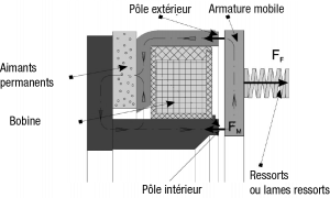
F M: magnetic force – F F: Spring force – Braking: no power supply to coil F M > F F –
Release : power supply to coil F M < F F
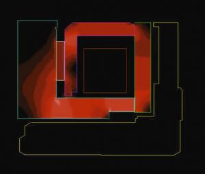
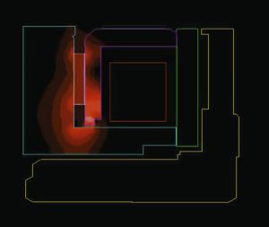
Flow principle of the flux:
 |
 |
|
“Braked” |
“Released” |
Braking:
The permanent “rare earth” magnets create a magnetic field, the lines of which are closed at the armature and the internal and external poles.
The armature passes through the air gap that separates it from the brake. It is then attracted to the fixed poles of the brake and consequently produces a braking torque due to friction.
– Parking brake: steel-on-steel friction surface.
– Dynamic braking: mixed friction surface (steel on moving armature – steel and friction material located between the poles on the brake body).
Release:
The power supply to the coil produces a magnetic field opposite to that of the permanent magnets, thus causing the moving armature to be released by the leaf springs – the immobilized shaft is now released.
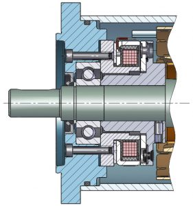
Various types of fixing are possible: see the product pages.
Installation example: brake 86 6 .. Series H:
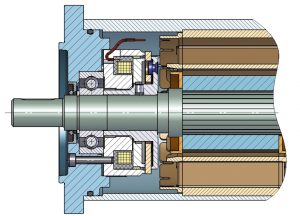
2 / Permanent magnet brake 86 6 .. – Series P New generation: High Torque
Safety braking through absence of current:
The brake is mounted on a fixed section and the moving armature is mounted on the shaft. The principle behind the operation of the series P brake is the same as for series H except for the fact that the flux flow is modified. The permanent magnets are no longer located at the rear, as in the case of series H, but between the poles. The High Torque brakes are used in high-tech equipment that
needs a very high static holding torque or demands a footprint that is even more compact than is available with the H version.
The series P brakes:
– operate perfectly from -40 °C to +120 °C and have a constant torque.
– do not exhibit any release problems when the supply voltage increases.
– generate torques that can reach values very much higher than are available with series H.
Compared to the series H brakes, the mean friction radius is greater (due to the proximity to the poles) and the flux is more effective, thus offering higher performance. They are used as static parking brakes.
Flow principle of the flux:
 |
 |
| “Braked” | “Released” |
Installation example: brake 86 6 .. Series P:
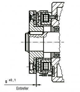
3 / Electromagnetic power-on brake 86 1 ..
Braking action through current emission:
The brake is mounted on a fixed section and the moving armature is mounted on the rotating shaft. Current emission at the coil creates a magnetic field that attracts the moving armature to the fixed poles, thereby creating a braking torque due to friction.
When the current is interrupted, the field is cancelled out and the moving armature is released from the friction surface, which in turn releases the shaft.
Installation example: brake 86 1 ..
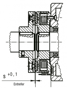
4 / Clutch 86 0 ..
The clutch consists of three main operating components:
– the coil (immobilized during rotation)
– the polar armature (at the top of the coil and fixed to the primary shaft)
– the moving armature (equipped with leaf springs and fixed to the secondary shaft)
Current emission at the coil creates a magnetic field that attracts the moving armature to the poles of the clutch’s polar armature. The primary shaft is thus coupled to the secondary shaft by friction.
When the current is interrupted, the field is cancelled out and the moving armature is released from the friction surface, causing the primary and secondary shafts to be separated.
Installation example: clutch 86 0 ..:
DEFINITIONS:
Air gap (mm):
An optimum operating air gap between the friction surfaces should be set during installation in order to guarantee correct operation. On these units, the air gap is located between the brake (or clutch) and the moving armature. The values for the air gap are indicated in the product pages.
Torque (Nm):
– The holding torque M4 is the static torque delivered when the unit is stopped. The torque M4 of the permanent magnet brakes is given for an ambient temperature of 120 °C.
– The torque M2 is the dynamic torque delivered by the unit at a given speed: in this case, the unit is equipped with friction material.
For any given unit, the static torque will always be greater than the dynamic torque.
Breaking-in:
The moving armature and the electromagnetic component are matched to one another because they are already broken-in ex works. They should be broken in again in the definitive installation in order to ensure that the maximum torques are obtained.
For example: in some cases the nominal torque of a series P – High Torque unit can be almost doubled after breaking-in.
The indicated breaking-in values must be respected.
Work or friction energy (J – Joule):
Work is only present when there is mechanical friction.
In the case of a brake, this corresponds to the kinetic energy that is acquired by the machine and transformed into heat in the brake during a dynamic braking operation.
In the case of a clutch, where there is a relative speed between the rotating primary shaft and the secondary shaft, it is the energy required to accelerate the secondary shaft. If the machine has to overcome a resistive torque immediately on start-up then this torque must be taken into account.
Work per operation W:
![]()
J = inertia of the assembly in movement in kg.m 2
ω= speed in radians per second
Temperature (°C):
The clutches and brakes described in this catalogue belong to class F; that is to say that the maximum temperature of the insulation at the coil is 155 °C.
Overall heating corresponds to the heating of the coil due to its electrical resistance and to the heating caused by any mechanical friction.
The habitual ambient operating temperatures are:
– series H brakes: -5°C to +120 °C
– series P brakes: -40 °C to +120 °C
Response time:
Operation times primarily consist of two elements:
– the electromagnetic reaction times (for values, see the product pages).
– the period required to establish the torque in the mechanical components (partly due to inertia and resistive torque).
An over-excitation (or overvoltage) in the coil or in a specific cable permits faster braking or release (please ask us).
Standard supply voltage:
The standard voltage is 24 V DC +5% / -10% at an ambient temperature of 20 °C.
Please note that in the case of permanent magnet brakes, it is necessary to specify whether the voltage is smoothed or rectified.
Nominal capacity (W – Watt):
The nominal electrical power consumed by the coil is indicated in the documentation for a nominal voltage and a temperature of 20 °C.
Cabling:
We recommend cabling with a diode and “free-wheel” resistance.

This cabling solution prevents electrical arcing when the current is interrupted (deterioration of the switch) and makes it possible to achieve a recall time that is almost as short as when the electrical control system is not protected by the diode and electrical resistance.

Timing belts or chains: 5 reasons to switch to timing belts
