A modular electric actuator is based on a simple idea: start with a standard mechanical platform and select only the components required for the intended motion. For engineering departments, integrators, and maintenance teams, this approach provides a useful middle ground between a fully standardized electric actuator and a custom solution developed to a technical specification.
The point is not simply to receive a disassembled actuator and put it together like a construction set. The real value of the kit lies in its modularity: stroke, force, speed, mounting, motor configuration, and control functions can be combined around a common architecture. This approach provides greater flexibility from the design stage onward and limits the need for custom solutions. That is exactly what we will explore through the operation and possibilities offered by the MS10 T.
Key takeaways from the article
- An actuator kit is based on a configurable standard architecture, not simply a shipment of separate parts.
- Modularity makes it possible to adapt the motion parameters without systematically starting over with a custom design.
- This approach simplifies engineering, integration, maintenance, and reuse of the same platform across multiple machines.
- It is particularly relevant when the required cycle rate and positioning accuracy remain compatible with a simple mechanical architecture.
- Binder Magnetic’s MS10 T is a concrete example of this approach applied to common industrial motion requirements.
Why manufacturers are increasingly interested in modular electric actuators
Between a fixed standard and a custom solution
When linear motion needs to be integrated into a machine, two opposite approaches often emerge. The first is to select an off-the-shelf actuator whose specifications are already defined in a catalog. The second is to use a custom solution when stroke, force, space, or control requirements fall outside the usual ranges.
The modular concept creates a third option. The core mechanical design remains standardized, but several components can be selected to adapt the actuator to the application. The manufacturer therefore does not redesign the entire actuator: it configures the elements that have a real impact on the motion to meet the specific requirements of the project.
A response to the diversity of machine designs
Within a workshop or machine range, requirements often change without being completely different: the stroke increases, the mounting changes, the load is higher, or the speed needs to be adjusted. A modular architecture makes it possible to keep a common platform while varying certain parameters. This approach can be particularly useful for a machine builder offering several versions of the same equipment.
How an electric actuator kit changes design and maintenance
An engineering process focused on the parameters that matter
With a modular linear actuator, the engineering team can work directly from the function to be performed: what stroke is required? What force must be transmitted? At what speed? How much space is available for the motor and mountings? This method avoids treating every new motion requirement as an entirely separate project.
A common platform that is easier to integrate over time
Standardizing some of the components can also simplify maintenance throughout the machine’s service life. When the same actuator family is used across several pieces of equipment, maintenance teams are already familiar with the architecture, interfaces, and adjustment principles. The number of part numbers to manage can also be streamlined.
A kit does not mean improvised design
Modularity remains governed by defined operating ranges. The goal is not to freely combine any components, but to select compatible variants within a system designed for that purpose. This framework preserves the simplicity of a standard solution while providing greater flexibility.
What are the benefits and limitations of a modular solution?
Selecting a kit-based linear actuator makes sense when the desired flexibility remains compatible with a standard mechanical platform. It therefore does not replace either simple standard actuators or custom-engineered solutions for highly specific requirements.
|
Approach |
Main benefit |
When to choose it |
|
Off-the-shelf standard actuator |
Fast selection and predefined specifications |
A straightforward need that exactly matches an existing part number |
|
Modular actuator kit |
Common platform with several easily configurable parameters |
A standard application requiring flexibility without a custom design |
|
Custom-engineered actuator |
Extensive adaptation to demanding application requirements |
Forces, strokes, environments, or functions outside standard ranges |
The right balance therefore depends less on the number of available options than on the gap between the actual requirement and the ranges supported by the architecture. The wider that gap becomes, the more relevant a dedicated engineering study and a custom actuator designed for the project become.
The MS10 T as a real-world example of a modular electromechanical actuator
A deliberately simple mechanical design
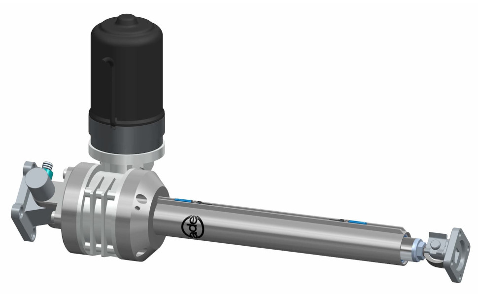
The MS10 T combines a trapezoidal lead screw with an integrated worm gear reducer. This architecture is designed for push and pull movements where reliability, robustness, and simplicity matter more than very high cycle rates or high positioning accuracy.
Configurable parameters around a single frame size
Around this platform, users can define the stroke, speed, force, and mounting type, among other parameters. The MS10 T covers strokes from 100 to 500 mm, speeds from 1 to 50 mm/s, and forces of up to 1,000 daN depending on the configuration. The motor is mounted perpendicular to the actuator axis, which also reduces the overall length and makes integration easier.
The kit is delivered complete and can be assembled at our factory. 3D files are also available for several common mounting configurations, helping the engineering team verify integration before finalizing the design. The MS10 T therefore demonstrates the value of the concept: the same mechanical platform can handle several motion requirements as long as the application remains within its operating range.
You can also consult our dedicated MS10 T technical documentation.
How can you tell whether an electromechanical actuator kit is right for your application?
Questions to ask before choosing
- Does the required motion fall within standardized stroke, force, and speed ranges?
- Is the cycle rate moderate, and is the positioning accuracy compatible with a simple mechanical design?
- Would the machine benefit from a common actuator platform across several variants?
- Do the available space, mountings, or controls require adaptation without justifying a fully custom design?
- Do the teams want to be able to integrate or assemble a configured solution themselves?
If several answers are yes, a modular approach is worth considering. Conversely, a very high cycle rate, high accuracy, a harsh environment, or out-of-range specifications may point to another actuator family for more demanding applications, or to a custom-engineered design when the technical input data are highly specific.
What to remember
The main advantage of an electric actuator kit lies in the modularity of its architecture. By keeping a standard platform and varying only the components required for the motion, it becomes possible to simplify the design without locking the solution into a fixed configuration. This approach is particularly well suited to common industrial applications, when requirements vary from one machine to another but remain within defined technical ranges. The MS10 T illustrates this approach with a simple mechanical design and several configuration options. Binder Magnetic can therefore offer this solution when the need falls between a standard actuator and a fully custom-engineered development.
FAQ about actuator kits and the MS10 T
Can an intermediate position be added to an MS10 T?
Yes. In addition to the two end-of-travel limit switches, a third or several intermediate limit switches can be provided. The number of positions therefore depends on the number of limit switches installed.
Can the MS10 T be equipped with force limiting?
Yes. A clevis equipped with an electromechanical load-sensing pin can protect the system in the event of overload or accidental jamming, in both pull and push directions.
Can the speed of an MS10 T be adjusted after installation?
On three-phase versions, the speed can be adjusted by varying the frequency. This makes it possible to adjust the speed and modulate the motion over the full stroke according to the desired result.
Are multiple 3D files available for integrating the MS10 T?
Yes. 3D files are available for strokes from 100 to 500 mm in three common configurations: 45° clevis, 0° clevis, and fixed body mounting with a spherical rod eye on the rod. Other versions are available on request. Please contact your local BINDER-MAGNETIC representative.
Can a brake be added to the MS10 T?
Yes. A position-holding and safety brake is one of the options available for this range. The electromagnetic brake can stop the actuator at a very precise position even at high travel speeds. It also ensures static position holding under variable loads or in applications with strong vibrations. It should be specified based on the needs of the application.