TECHNICAL INFORMATIONS OF SYNCHRONOUS TRANSMISSIONS
TIMING BELTS
Thanks to its reliability and low cost a belt used to transmit motion is an essential element in the design of mechanisms.
BINDER magnetic timing belts are made of high-strength polymers and tension members which lend them mechanical properties that enable them to be adapted to all industrial applications.
Main mechanical properties :
- Synchronous drive
- Constant length, no elongation
- Low noise level (use of a polyamide coating on the tooth side, PAZ)
- Wear-resistant
- Maintenance-free
- Extremely flexible (enhanced by the use of high-flexibility tension members)
- Maximum speed up to 80 m/s
- Precise angular position
- Little space required
- Favourable power-to-weight ratio
- Low pre-tension, low bearing load compared with other technologies
- Permits large centre distances
- Permits large transmission ratios
- High degree of efficiency up to 98%
Several factors play a role in the choice of belt, such as tooth profile, tension members, material, and field of application. These elements are described in this chapter.
1 / Force transmittable by the teeth :
| Load distribution | Strain distribution | |
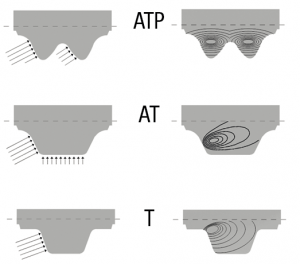 |
The force transmittable by the teeth depends on the rotational speed and on the maximum load value that each tooth can transmit in continuous operation. These values are shown in the diagrams for each timing belt type on the pages for each belt. A timing belt is correctly dimensioned if the force transmittable by the teeth is not exceeded. It is generally not necessary to add a safety factor, see section “Safety factor”. |
|
The working load can be distributed better by more teeth in mesh in the toothed pulley. The following maximum numbers of teeth must be used for the calculations:
-CONTI® Synchrochain, CONTI® Synchroforce, CONTI® Synchrotwin and BRECO® joined belts (V): maximum 6 teeth
– CONTI® Synchrodrive, Synchroflex® and BRECOflex® belts: maximum 12 teeth
– Synchroflex® GEN III belts: maximum 16 teeth
2 / Tooth profiles :
Different types of profiles are available based on the belt selected:
T profile: older-generation profile which is no longer adapted to power transmission. It is still used to transport and convey light loads thanks to small wrap diameters.
![]()
AT profile: standard profile adapted to power transmission and transmission of heavy loads. If has superior synchronisation and positioning precision.
![]()
ATP profile: new-generation profile adapted to transmission of heavy loads. It can combine positioning precision and zero backlash with reversal of direction.
![]()
HTD profile: primarily adapted to basic power transmission not requiring positioning precision.
![]()
STD profile: further development of the HTD profile which provides improved meshing and a reduced noise level.
![]()
CTD profile: the CTD profile is adapted to very high power transmissions and to extreme dynamic stresses.
![]()
3 / Teeth safety factor:
The formula for determining the width does not take account a safety factor. Basically, if the width calculation has been made with perfectly known peak torques, there is no reason to provide for it. A verification of the tension member resistance must also be performed.
In case of doubt it is advisable to take account of the peak torque or an “accidental” overtorque which the belt can be induced to transmit.
Other parameters such as braking torque, dynamic irregularities and inertias are necessary for determination purposes:
- Braking can possibly exceed the load resulting from nominal utilisation or starting conditions.
- Oscillations and concentrated overloads can be added to the nominal load applied to the tensioned span.
- Centrifugal masses or rotating masses generally influence the regularity of the drive. These elements must be taken into consideration if the centrifugal masses apply a supplementary load to the belt.
4 / Force transmittable by the tension members FN:
![]()
The timing belt is correctly dimensioned if the maximum allowable value of the tension member tension is not exceeded. The values shown in the tables for FN correspond to a constant load limit on the tension members.
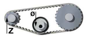
5 / Wrap stress:
| Drive configuration without contra-flexure |
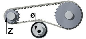
Drive configuration with contra-flexure |
 |
 |
To guarantee correct operation, we recommend a minimum number of teeth and a minimum wrap diameter to suit the belt type.
Note:
The configuration of timing belts “with contraflexure” (for example by tension roller) generally imposes a larger minimum number of teeth and a larger minimum diameter.
6 / Pre-tension force:
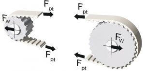 |
The purpose of the pre-tension force Fpt is to guarantee a minimum tension during operation on the slack side in order to ensure that the teeth mesh correctly on the pulleys. The pre-tension force to be applied to the run depends on the maximum tangential force FN, the belt length LB (number of teeth ZB) and the drive configuration. The bearings must be dimensioned to support Fw. |
Consequences of incorrectly set pre-tension:
Insufficient pre-tension:
- The teeth on the slack side run up on the teeth on the driven pulley and cause teeth to jump,
- Wear on the faces caused by friction during meshing,
- Breakage caused by excessive elongation following a complete “run-up” on the teeth or the flanges,
Excessive pre-tension::
- Overloading of the bearings,
- Reduced transmittable power,
- Excessive noise,
- Possible axial misalignment,
- Premature tooth wear.
Solution: measurement with the SM5 tension meter
It is essential to apply adequate pre-tension to the belt so that it does not deteriorate prematurely. The BINDER magnetic SM5 tension meter enables the user to measure the natural frequency of a resonant belt run when stopped.
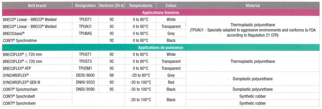
7 / Polymers :
7.1 Qualities of standard polymers:
7.2 Design of special polyurethane belts:
For BRECO® linear (M), BRECO® welded (V) and BRECOFLEX® belts.
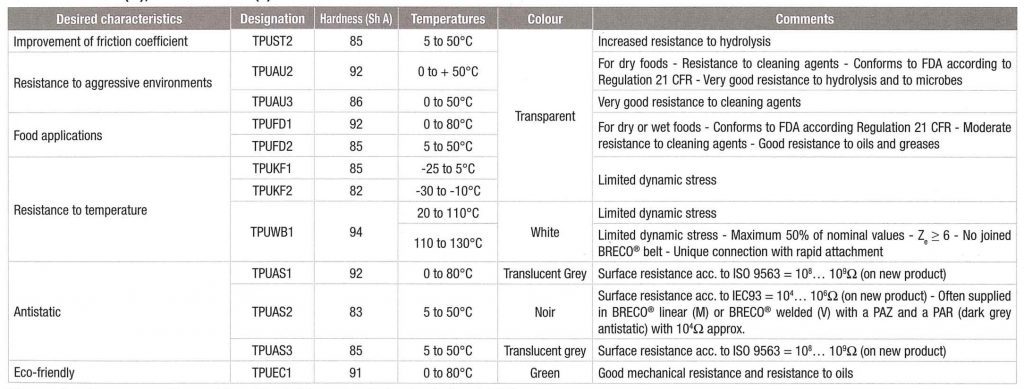
These polyurethanes cannot be used for all the belt types (contact us for further details)..
For SYNCHROFLEX® belts
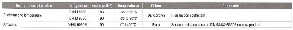
7.3 Design of polypropylene belts:

7.4 BRECOgreen ®:
|
This belt is partly made of eco-friendly polyurethane that comes from original renewable materials. – Mechanical polyurethane characteristics identical to the standard – Can be made in all the versions:
° With profiles ° With coatings – Can be joined by glueing or welding |
 |
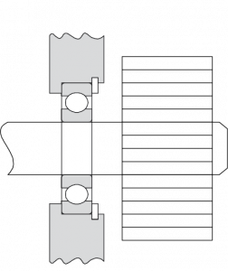
8 / Influence on pulleys:
The choice of a high-performance belt from BINDER magnetic is the right solution for:
- reducing inertia
- reducing the space required, and hence the cost
- reducing the bending moment (better axial parallelism)
- improving efficiency.
| Standard solution | High-performance solution |
 |
 |
9 / Tension members of belts:
Each type of belt has tension members which give its well defined mechanical characteristics. Thanks to this the belts maintain an elasticity without elongation.
A tension member is comparable to a spring subjected to strain deformation. The tension member is deformed proportionally in the elasticity phase under stress in accordance with Hooke’s Law.
9.1 Tension members of polyurethane (PU) belts:
Standard PU belts are reinforced by galvanised steel tension members. These tension members enable the belts to maintain their longitudinal stability. However, like all metals, steel is deformed under load according to Hooke’s Law. This law describes deformations under load in the elasticity phase. The value of the force FN (maximum permissible nominal force) is specified for each pitch on the profile pages. Elongation of the belt is proportional to the force applied to the wire.
Hooke’s Law:

Bifilar design z + s
| This is achieved by an opposed-twist arrangement which enables it to limit the belt pressure on the flanges, resulting in improved efficiency and reduced wear on the faces. | 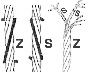 |
Tension members of SYNCHROFLEX ® et BRECOFLEX ® belts
These belts, produced by extrusion or “endless” moulding, are fitted with continuous tension members. Two options:
- Monofilar (one tension member per belt): this is the case with standard SYNCHROFLEX® and BRECOFLEX® belts up to 710 mm.
- Bifilar Z + S opposed twist (two tension members per belt): this improvement is already effective on the majority of BRECOFLEX® belts starting from 710 mm in length and on all SYNCHROFLEX® GEN III belts. It has been possible to increase the number of tension members on the latter belts. As a result the transmittable tangential force (Ft) is increased by 45% for SYNCHROFLEX® GEN III belts.
Tension members of BRECO® linear (M) and BRECO® welded (V) belts
These belts, produced by linear extrusion, are fitted with parallel tension members.
9.2 Special tension members:
– High-flexibility galvanised steel tension member (E).
 |
 |
| Standard tension member (ST) | High-flexibility tension member (E) |
For E high-flexibility tension members the section is distributed to a much higher number of finer wires, reducing the bending stresses accordingly. The advantage offered by the E tension member is better bending strength.
Timing belts with E tension members must preferably be used for multiple-pulley drives or where the contraflexures are more frequent.
– Reinforced steel tension member
– Stainless steel tension member: this tension member transmits a little less force than the normal steel tension member but has good resistance to chemical attacks.
– Aramide fibre tension member: this tension member has good resistance to certain chemical agents but this fibre has the drawback of creeping over time. It is not suited to dynamic stress.
The use of these last three special tension members lends belts different mechanical and elastic characteristics. We can advise you on choosing a specific variant.
9.3 Tension members of CONTI ® SYNCHROBELT and CONTI ® SYNCHROCHAIN belt:
CONTI® SYNCHROFORCE belts and CXP belts are reinforced with twisted glass fibre tension members while CXA belts and CONTI® SYNCHROCHAIN belts are reinforced with an aramide fibre tension members. Carbon CONTI® SYNCHROCHAIN belts are reinforced with carbon tension members.
10 / Service conditions:
Various service parameters must be observed in order to transmit a torque under good conditions with regard to service life, noise level, bearing load, and backlash:
- Clean surrounding area – Ambient temperature
- Good pulley quality – Observance of minimum diameters
- Good pre-tension
Fitting with a fixed centre distance necessitates belts with a more exacting length tolerance and with more precise machining (it is essential to consult our technical department).
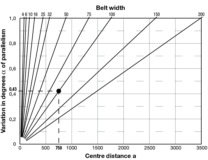
11 / Axial parallelism:
 |
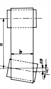 |
To avoid side forces on the guide flanges, the angular distance “a” between two shafts must be lower than the belt width “b” is large and the centre distance short (refer to the diagram above and do not exceed ±1°).
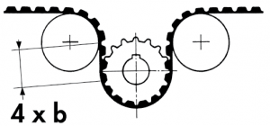 |
For this same reason we recommend that you observe if possible the ratio of 1 to 4 between the belt width “b” and the length of the run between two pulleys or return rollers. |
An axial misalignment of the pulleys generates a force of lateral pressure by the belt on the flanges which causes wear of the belt face and an imbalance in the distribution of loads.
12 / Noise level of a transmission:
The noise level of a transmission depends on a number of parameters: pre-tension, speed, surface quality of the pulleys, quality of cut and hardness of the PU, etc. We have SFAT – ATP – BATK10 profiles to reduce noise (consult our technical department).
13 / Alignment of pulleys – guidance:
Belt guidance is a fundamental element in the correct functioning of a transmission. It is a question of obtaining minimum lateral forces and of reducing friction losses.
 |
Attend in particular to the alignment of the pulleys and to the length of the runs preceding the guidance of the belts. The economic aspect must be taken into account, since flanges are more cost-effective for small pulleys than for big pulleys. |
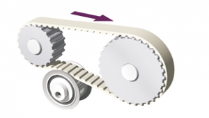 |
Guidance of the belts can be effected on one or more rollers. When a flanged tension roller is used it must be positioned in such a way as to obtain a belt run that is as long as possible before the guidance (the tension roller must preferably be positioned on the slack side). |
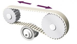 |
If the direction of rotation changes, the tension roller must preferably be positioned in the middle of the belt run. Avoid runs that are too short before the guidance and this to avoid a lateral load on the belt. |
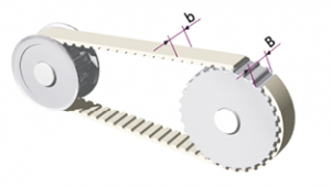 |
For a belt width “b” a flanged pulley width “B” is assigned in order to guarantee sufficient lateral play. In certain specific cases, for example for belts of large lengths or for vertical axes, it may be necessary to provide more than two flanged pulleys. |
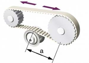 |
In general all the lengths of the belt runs must be 4 times the width of the belt. a=4b |
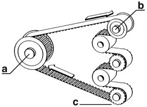 |
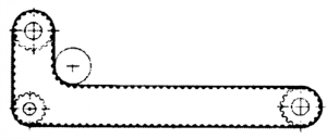
For multiple shafts, where there is one direction of rotation, it is sufficient to flange-mount two pulleys (a and b). It is recommended to use belts with bifilar tension members to limit the loads on the flanges. |
Alignment
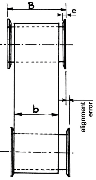 |
The alignment error must not be greater than the value: (B-2e) – (bmax+1 mm) |
14 / Method of checking the length tolerances of belts:
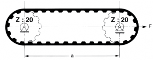
Checking method
The measurements are conducted according to DIN 7721 on a bench with two “standard” pulleys which are forced apart by a force F called the “measurement load”.
Measurement process: to measure the effective length of a belt the latter must have completed at least two full rotations such that it is correctly positioned and that the “measurement load” is equally distributed between the two runs of the belt.
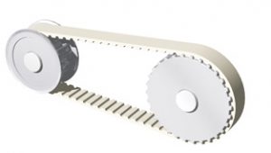
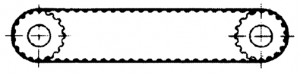
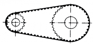
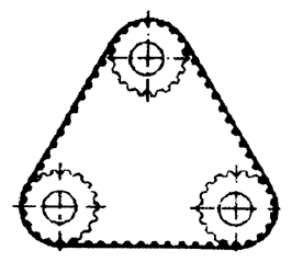
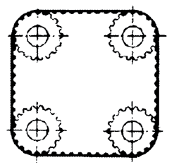
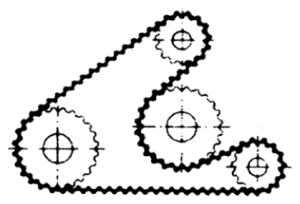
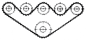
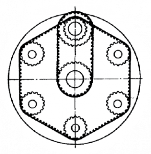
15 / Examples of use:
Rotational motion
 |
 |
 |
 |
 |
 |
 |
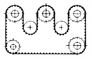 |
 |
Linear motion
| Toothed rack secured flat on a base (glueing or clamping). IMPORTANT: SPECIAL TOOTHFORM. | 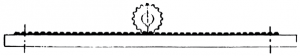 |
| Pulleys with a large number of teeth engaged. Little elongation of the moving belt, wich is going to engage in the glued or clamped belt. |  |
| Fixed motor and permanently rotating belt. The belt is stopped in its rotation by a brake, this induces the linear motion in one direction. The return motion is effected by an external linear force. | 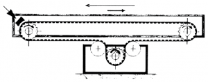 |

Conveyor belt maintenance in industry: saving time and money
