TECHNICAL EXPLANATIONS RELATING TO ELECTROMECHANICAL TRANSMISSIONS
MAIN SELECTION CRITERIA FOR ACTUATORS

Stroke (mm – Millimetre):
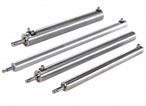
The specified stroke determines the maximum distance travelled by the actuator rod. This stroke can be preset ex works to meet your particular needs and, if necessary, you are able to adjust certain actuators yourself.
Read the service instructions carefully before making any adjustments.
Centre distance (mm – Millimetre):
Dimensions located between the fixing axis of the rod and the fixing axis of the body of the actuator when the rod is retracted or extended.
Force (N – Newton) :
The specified force corresponds to the actuator rod’s nominal axial thrust or tractive force when the actuator is switched on. When calculating the required force, it is necessary to take account of unpredictable climatic factors (wind, snow, etc.) The actuators must not be subject to radial force and are not designed to withstand the application of torque at the rod.
Speed (mm/s – Millimetres per second) :
The specified speed corresponds to the speed of travel of the rod when the actuator is switched on. When DC motors are used, the speed may vary slightly as a function of the load.
Supply voltage (V – Volt):
Three voltages are available depending on the model:– 24 V DC– 230 V 1AC– 400 V 3AC
Read the service instructions carefully before switching on the product.
Service factor (SF in % or S):
The service factor corresponds to the maximum period of operation of the actuator motor at + 20 °C. Limiting the period of operation keeps the motor temperature below the permitted limit. If this is exceeded then the motor may be damaged. Some electrical actuators are equipped with a thermal relay. However, this does not provide protection against overloads or certain forms of overheating.S2: operation for a short period, i.e. 5 minutes continuously followed by a stoppage of sufficient length for the motor to cool.S3 – 15 %: corresponds to maximum power supply for 90 seconds every ten minutes.
Protection (IP in accordance with standard IEC 60529):
The protection (in accordance with standard IEC 60529 – IP code) of an actuator refers to its capacity to prevent dust or water from penetrating into the body of the unit. The products in this catalogue have IP65 or IP67 protection depending on the model.
Actuator material (material no.):
The body of the actuator can be manufactured from different materials depending on the model.– Stainless steel 1.4301. Good corrosion resistance equivalent to 304 in the US – ALSI standard. (This steel is not suitable for chlorinated or extremely saline environments).– Stainless steel 1.4571. Very good corrosion resistance equivalent to 316Ti in the US – ALSI standard.– Anodized aluminium for enhanced corrosion resistance.
Options: encoder potentiometer (to identify the position of the rod)
An encoder or potentiometer can be installed as an option in order to define the position of the actuator rod. This is necessary, in particular, in order to move to positions between the end-of-stroke limits. These options depend on the model.– The encoder option makes it possible to count the number of pulses per motor revolution and therefore per mm of stroke. It is incremental and if there is no electricity supply, the encoder will not memorize the rod position. In this case, it is necessary to return to the electromechanical end-of-stroke limit positions in order to reinitialize the values.– The 10-revolution, 10KΩ rotary potentiometer can be installed in Econom actuators. The electrical voltage at the terminals will vary in proportion to the position of the rod on the original nominal stroke. If there is an interruption to the electricity supply, the position information will be retained.
Irreversibility:
Irreversibility is defined as the ability of an actuator to remain in its position even if an external force acts on the rod. All the actuators in this catalogue are irreversible at the maximumapplied force.
Latest news
- Jan 19, 2026
Environment: Binder Magnetic improves its EcoVadis score
- Nov 13, 2025


