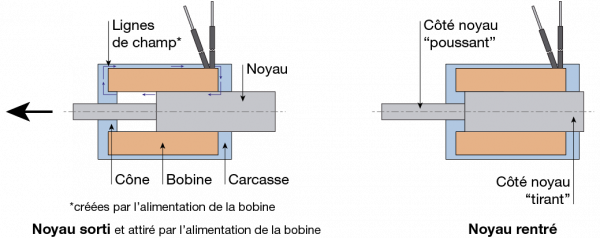
When the coil is powered, the solenoid generates magnetic field lines that close at the plunger. This induces a load and causes the plunger to move. When there is no current, the plunger remains in its position and is released (except in the case of monostable and bistable solenoids). The plunger is then returned to its original position by means of external forces (spring, weight, lever, etc.).
1/ Forces :
Magnetic force (F)
The attractive magnetic force (N) is the force that is exerted on the plunger and causes it to move. The forces indicated in the curves presented in this catalogue have been calculated:
– for a nominal voltage (Un) -10%
– for an ambient temperature +35 °C for KENDRION products and +25 °C for BINDER Magnetic products
– “hot” coil.
Definition of “hot” coil
– Coil at ambient temperature: when no power is applied to the solenoid, the temperature of the winding is the ambient temperature.
– “Hot” coil: the temperature of the coil is then the temperature obtained by adding the ambient temperature to the intrinsic heating due to the power supply to the solenoid at the limit of its duty factor (see § “Operating cycles”).
Available magnetic force (Fh)
Magnetic force (N) obtained after subtracting or adding the weight of the plunger (in the vertical position) and the force of the return spring.
Magnetic force at end of stroke
The magnetic force (N) obtained at the plunger when this has arrived at the end of its stroke or its mechanical stop (stroke 0 mm).
Residual force
The holding force (N) that persists due to remanence when the current is interrupted.
2/ Function :
The functions associated with the shape of the plunger:
– Attraction function: the action of the magnet pulls objects towards it
– Repulsion function: the action of the magnet pushes objects away from it
– Attraction/repulsion function: the action of the magnet pulls objects towards it on one side of the plunger and pushes objects away from it on the other side.
Single-stroke solenoid:
The plunger is attracted by the coil in the solenoid when current is applied. It is released again when the current is interrupted.
Dual-coil solenoid:
The plunger that runs through the unit is attracted on one side by one of the two coils and is subsequently attracted by the other coil as current is alternately applied to them. The plunger therefore travels through the defined stroke in both directions. It is released again when there is no current.
Monostable solenoid:
The plunger is attracted by the coil in the solenoid when current is applied and continues to be held in position when there is no further current due to the presence of a permanent magnet. Inverting the polarity of the power supply to the plunger cancels out the holding force of the permanent magnet and the plunger is released again.
Bistable solenoid:
The solenoid is equipped with two coils and, when current is applied, each coil attracts the plunger that passes through the unit at each end of its stroke. The plunger is held stably at each end of its stroke by means of permanent magnets.
3/ Stroke:
Magnetic stroke (s):
Distance (in mm) travelled by the plunger from the starting position through to the end-of-stroke position. In its starting position, a single-stroke solenoid is often located outside of the coil.
The space requirement diagrams in this documentation represent the plunger in its starting position and an arrow on the plunger indicates the direction of movement when current is applied.
Start-of-stroke position (s1 ):
The starting position of the plunger before it executes the stroke (the plunger is extended).
End-of-stroke position(s0):
The target position of the plunger after it has completed its stroke (the position of the plunger is retracted and corresponds to 0 mm on the curves).
Characteristic curve for magnetic force / stroke:
Curve indicating the magnetic force at the plunger as a function of the plunger’s position.
A distinction is made between three forms of characteristic curves:
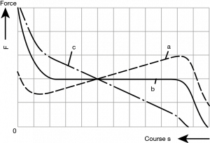
a. Ascending curve: appropriate for working with a spring
b. Horizontal curve: appropriate for working with constant loads
c. Descending curves: only on demand
Function of the plunger:
Most solenoids are equipped with a plunger that passes through the unit.
When this plunger moves, there is therefore one side that attracts and another that repels.
Each of the two sides can be used to perform a function.
Voltage, current and power:
Nominal voltage (Un):
The supply voltage (in V) defined for the solenoid.
The permitted tolerance for the nominal supply voltage to the solenoids is between +5% and -10% in order to obtain the forces indicated in the curves.
Overexcitation:
Overexcitation of the coil by means of an overvoltage during the period of movement of the plunger makes it possible to reduce the in-vacuum attraction period by up to a factor of 4.
This overvoltage can reach as much as four times the nominal voltage provided that the magnetic circuit will accept this.
In such cases, the duty factor has to be recalculated (consult us and see the information given for the Duty Factor).
We can supply an electronic overvoltage board.
Nominal current (In for DC current):
Intensity of the current (in A) consumed by the coil at a temperature of 20 °C and at the nominal voltage (Un). The nominal current is calculated by dividing the consumed power (Pn in W) by the nominal voltage (Un in V).
To determine the maximum current consumed by the solenoid, use the following formulae:
![]()
-P : power (in W).
I : current (in A) – Variable as a function of the temperature and the power supply.
U : min. voltage (in V) – Variable as a function of the power supply.
R : resistance (in Ω) – Variable as a function of the temperature.
Nominal consumed power (Pn):
Capacity (in W) of the coil at the nominal voltage and at a coil temperature of 20 °C. It is calculated by multiplying the nominal voltage (Un in V) by the nominal current (In in A).
Energy savings:
Our electronics board makes it possible to greatly reduce solenoid power consumption. Solenoids can also be designed with dual coils in order to reduce the current: in this case, one coil attracts the plunger and the other holds it in place (the current consumed by this second coil is considerably lower).
Electrical resistance:
Electrical resistance of the coil at 20 °C (in Ohms: Ω) – Manufacturing tolerance: ±10%.
Change of electrical resistance of the coil as a function of the ambient temperature:
The current intensity at the coil is a function of its electrical resistance.
The electrical resistance Ω of an electrical conductor varies with its temperature as follows:
![]()
-R ( ) : resistance (in Ω) at a given temperature.
-R0 : resistance (in Ω) at 20 °C.
-0.004 : coefficient associated with the temperature-related change in the electrical resistance of copper.
-∆ : temperature difference in °C between 20 °C and the temperature in the coil.
Take account of this change in the formula for calculating the current.
– I : current intensity (in A).
– P : electrical power (in W).
– R : resistance (in Ω) of the coil
For example, a solenoid with a resistance of 10 Ohms at 20 °C will have a resistance of 9.2 Ohms at 0 °C and 12.4 Ohms at an ambient temperature of 80 °C.
It should also be noted that applying a current to the coil results in a heating cycle that reduces the current.
Wiring diagram:
There are many different possibilities. However, we recommend that you use a diode and resistor in parallel. In effect, the interruption of the power supply to the coil causes a voltage peak at the control switch, which in turn generates an electric arc that risks damaging various components. This phenomenon is associated with the induction coil.
By wiring as indicated below, it is possible to restrict this arc.

R(Ohm) = 7 * R(Ohm) of the coil
Wiring in this way also makes it possible to limit the return time of the plunger.
Operating cycles:
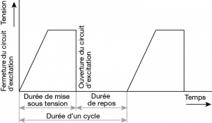
Energized period:
Period between the application of current to the coil and the interruption of this current.
De-energized period:
Period between the removal of the current and the subsequent application of current to the coil.
Duty factor (DF):
The duty factor (in %) corresponds to a ratio between the period during which the solenoid is active (Du) and the reference period (Dt) at +35 °C.
Du : effective total period during which the solenoid is powered during a reference period (Dt).
Dt : reference period, which is defined by our factory for each unit (between 2 and 5 minutes).
Calculation of the duty factor:
![]()
Example: Du = 2 min of application of current during a period (Dt) of 5 min for the unit / Dt = 5 min > DF = 2/5 x 100 = 40%
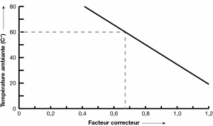
Change in the duty factor as a function of the ambient temperature:
If the ambient temperature is different from +35 °C then the table below should be used:

Example: a solenoid with a duty factor of 25% used at an ambient temperature of 60 °C is subject to a correction factor of 0.67.
The new duty factor is therefore 25% x 0.67 = 16.75%.
Response times:
These define the movement times of the plunger during attraction (pull-in) or return. The indicated values (in ms) are those obtained at nominal voltage, in horizontal position, for a full stroke and with a load corresponding to 70% of the magnetic force. This information is purely indicative and depends on several factors.
CONDITIONS OF USE:
Continuous power supply: 100%
 |
The period during which current is applied is sufficiently long for the solenoid’s limit temperature to be almost reached. For this type of application, choose a duty factor DF 100%. |
See the section on operating cycles and the duty factor.
Intermittent power supply:
 |
The power supply and rest periods alternate in a regular or irregular way. The rest periods allow the coil of the solenoid to cool down and keep the solenoid at an acceptable temperature level. |
See the section on operating cycles and the duty factor.
Short-term power supply:
 |
The periods during which current is applied are sufficiently short to make it impossible for the solenoid’s limit temperature to be reached. The periods of rest between each power supply period are long enough for the solenoid to be able to cool down sufficiently. |
See the section on operating cycles and the duty factor.
Plunger guides:
As it moves, the plunger slides along guides which are subject to wear as a function of the number of operations.
The plunger can be guided directly at the coil body or by means of self-lubricating PTFE or bronze slide rings.
A distinction is made between three durability categories:
– limited: approximately 500,000 operations
– medium: between 1 and 10 million operations
– high: more than 10 million operations
The category is indicated in the corresponding product description. These estimates are based on a clean ambient environment (no dust or grease), a lack of any radial load, an ambient temperature between 1 °C and 35 °C and relative humidity of less than 50%.
TEMPERATURE:
Ambient temperature V13 (°C):
Mean value of the temperatures around the solenoid.
Operating temperature V23 (°C):
Temperature reached when electricity is applied to the coil of the solenoid. The solenoid heats up when current is applied to the coil because this acts as an electrical resistor and therefore produces heat.
Limit temperature V21 (°C):
Maximum permitted temperature for the coil of the solenoid. This temperature is defined by the insulation class (see information below).
Temperature increase V32 (°C):
Difference in temperature between the coil of the solenoid and the ambient temperature. This difference occurs when current is applied to the solenoid.
Temperature increases of +70 °C are quite frequent when solenoids are used at the limit of the duty factor (however, this value is purely indicative).

It should be noted that:
-V21 must always be higher than V23
-V32 = V23-13
Insulation class of the coil:
The insulating varnish of the coil’s copper wire permits electrical insulation between the coil’s turns. The thermal insulation class, which is associated with this varnish, indicates the maximum permissible temperature of the coil as it heats up. Choosing the right insulation class allows the solenoid to function correctly under the voltage, duty factor and ambient temperature conditions defined for the unit.
|
Insulation class |
Limit temperature (°C) V21 |
Maximum heating at an ambient temperature of 35 °C |
| Y | 90 | 50 |
| A | 105 | 65 |
| E | 120 | 80 |
| B | 130 | 90 |
| F | 155 | 115 |
| H | 180 | 140 |
| C | 200 | >200 |
Maximum ambient operating temperature:
The limits of the ambient operating temperature are often between -5 °C and +35 °C (beyond this, please contact us because numerous solutions are available). Below 0 °C, a risk of frost that can block the plunger is often observed.
Important: the strength of the solenoid is linked to the current and, consequently, to the resistance of the coil, which changes with temperature.
AMBIENT OPERATING CONDITIONS:
Ambient operating temperature:
The duty factor DF corresponds to an ambient temperature of up to +35 °C (beyond this, please contact us).
Relative humidity:
The level of humidity in the ambient air must be less than 50% when the ambient temperature is greater than 40 °C. At ambient temperatures below 40 °C, the air humidity may be higher (for example, 90% humidity at an ambient temperature of 20 °C).
The occasional condensation of water in the ambient air must be taken into account.
Special operating conditions:
If it is not possible to respect the normal operating conditions then we will suggest solutions appropriate to your needs, for example: a higher insulation class, special paint, enhanced protection, etc.
Extreme environments:
The solenoids must be protected against atmospheres that contain a large quantity of abraded particles or dirt, corrosive gases, etc.
Protection :
Corrosion protection of metal surfaces: galvanic treatment.
Protection against the penetration of liquid or solid foreign bodies into the solenoid: standard IEC 60529 (IP code).
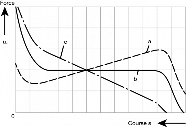
a. Courbe croissante : appropriée pour travailler avec un ressort
b. Courbe horizontale : appropriée pour travailler avec des efforts constants
c. Courbe décroissante : uniquement sur demande
Fonction du noyau :
La plupart des électro-aimants sont équipés d’un noyau traversant l’appareil.
Lors du déplacement de ce noyau, il y a donc un côté tirant et un côté poussant.
Les 2 côtés peuvent être utilisés pour assurer une fonction.
Tension, intensité et puissance :
Tension nominale (Un) :
La tension d’alimentation (en V) définie pour l’électro-aimant.
La tolérance acceptable sur la tension d’alimentation nominale pour les électro-aimants est de +5% et de -10% pour obtenir les forces des courbes.
Surexcitation :
Une surexcitation de la bobine par surtension, pendant la durée de déplacement du noyau, permet de réduire jusqu’à 4 fois la durée d’attraction à vide.
Cette surtension, lorsque le circuit magnétique l’accepte, peut aller jusqu’à 4 fois la tension nominale.
Le facteur de marche devra être recalculé (nous consulter et voir les informations sur le Facteur de Marche).
Nous proposons une carte électronique de surexcitation.
Intensité nominale (In courant continu) :
Intensité (en A) consommée par la bobine à une température de 20oC et à une tension nominale (Un). L’intensité nominale est calculée en divisant la puissance consommée (Pn en W) par la tension nominale (Un en V).
Pour déterminer le courant maxi consommé par l’électro-aimant utiliser les formules suivantes :
![]()
-P : puissance (en W).
-I : intensité (en A) – Variable en fonction de la température et de l’alimentation.
-U : tension mini (en V) – Variable en fonction de l’alimentation.
-R : résistance (en Ω) – Variable en fonction de la température.
Puissance nominale (Pn) consommée :
Puissance absorbée (en W) de la bobine à la tension nominale et à une température de bobine de 20°C. Elle est calculée en multipliant la tension nominale (Un en V) par l’intensité nominale (In en A).
Économie d’énergie :
Pour ce qui est de notre carte électronique, elle permet de réduire considérablement la consommation d’un électro-aimant. Un électro-aimant peut également être étudié avec une double bobine pour diminuer le courant ; dans ce cas, une bobine est destinée à l’appel du noyau et l’autre bobine au maintien de celui-ci (pour cette 2 e bobine, le courant consommé sera donc nettement plus faible).
Résistance électrique :
Résistance électrique de la bobine à 20°C (en Ohm : Ω) – Tolérance de fabrication : ±10%.
Evolution de la résistance électrique de la bobine en fonction de la température ambiante :
L’intensité de la bobine est fonction de la résistance ohmique de celle-ci.
La résistance Ohmique Ω d’un conducteur électrique varie avec la température ainsi :
![]()
-R ( ) : résistance (en Ω) à température donnée.
-R0 : résistance (en Ω) à 20°C.
-0,004 : coefficient lié à l’évolution de la résistance électrique du cuivre avec la température.
-∆ : différence de température en °C entre 20°C et la température dans la bobine.
Tenir compte de cette évolution dans la formule de calcul du courant
– I : intensité (en A).
– P : puissance électrique (en W).
– R : résistance (en Ω) de la bobine
Par exemple, un électro-aimant d’une résistance de 10 Ohm à 20°C aura 9,2 Ohm à 0°C et 12,4 Ohm à 80°C ambiant.
A noter aussi que la mise sous tension de la bobine implique un cycle d’échauffement entraînant une diminution du courant.
Schéma de câblage :
De nombreuses possibilités existent, toutefois nous vous conseillons le câblage avec diode et résistance en parallèle. En effet, la coupure de la bobine alimentée provoque un pic de tension sur l’interrupteur de commande générant ainsi un arc électrique qui peut détériorer différents composants. Ce phénomène est lié à la self de la bobine.
Le câblage ci-dessous permet de limiter cet arc.

R(Ohm) = 7 * R(Ohm) de la bobine
Ce câblage permet aussi de limiter la durée de retour du noyau.
Cycles de fonctionnement :

Période sous tension :
Durée entre la mise sous tension et la coupure de la tension de la bobine.
Période sans tension :
Durée entre la coupure de la tension et la mise sous tension de la bobine.
Facteur de marche (FM) :
Le facteur de marche (en%) correspond à un rapport entre les durées de mises sous tension de l’électro-aimant (Du) et la durée de référence (Dt) à +35°C.
Du : durée totale effective maximum d’alimentation sur une durée de référence (Dt).
Dt : durée de référence, définie par notre usine, pour chaque appareil (entre 2 et 5 min)
Calcul du facteur de marche :
![]()
Exemple : Du = 2 min réellement alimentées sur une période (Dt) de 5 min pour
l’appareil / Dt = 5 min > FM = 2/5 x 100 = 40%
Évolution du facteur de marche en fonction de la température ambiante :
Si la température ambiante est différente de +35°C le tableau suivant est à appliquer :
Exemple : un électro-aimant avec un facteur de marche de 25% utilisé à une température ambiante de 60°C a un facteur correcteur de 0,67.
Ainsi le facteur de marche devient 25% x 0,67 = 16,75%.
Temps de réponses :
Tout d’abord, ils définissent la durée de déplacement du noyau lors de l’attraction ou du retour. Les valeurs mentionnées (en ms) sont ainsi obtenues avec la tension nominale, en position horizontale, pour la course totale et avec une charge correspondante à 70% de la force magnétique. Par ailleurs, ces données sont indicatives et dépendent de nombreux critères.
CONDITIONS D’UTILISATION :
Alimentation en continu : 100%

La durée de mise sous tension est suffisamment longue pour que la température limite de l’électro-aimant soit presque atteinte. Pour ce type d’application choisir un facteur de marche FM 100%.
Voir le chapitre sur les cycles de fonctionnement et le facteur de marche.
Alimentation intermittente

Les durées de mise sous tension et de repos alternent en une succession de durées, régulières ou non. Les temps de repos permettent alors à la bobine de l’électro-aimant de se refroidir et de maintenir l’électro-aimant à un niveau de température acceptable.
Voir également le chapitre sur les cycles de fonctionnement et le facteur de marche.
Alimentation de courte durée

Les durées de mise sous tension sont suffisamment courtes pour que la température limite de la bobine de l’électro-aimant ne puisse pas être atteinte. Les repos entre chaque période d’alimentation sont assez longs pour que l’électro-aimant puisse suffisamment se refroidir.
Voir aussi le chapitre sur les cycles de fonctionnement et le facteur de marche.
Guidage du noyau
Lors de son déplacement le noyau glisse sur des guidages qui s’usent selon le nombre de manœuvres.
Le guidage du noyau peut être réalisé directement sur le corps de bobine ou à l’aide de bagues de glissement auto lubrifiées, PTFE ou bronze.
On distingue 3 catégories de longévité :
– limitée : environ 500 000 manœuvres
– moyenne : entre 1 et 10 millions de manœuvres
– élevée : supérieure à 10 millions de manœuvres
Cette indication est mentionnée sur le descriptif du produit. Ces estimations correspondent en revanche à un milieu ambiant propre (absence de poussière ou de graisse), une absence d’effort radial, une température ambiante située entre 1°C et 35°C et une hygrométrie relative inférieure à 50%.
TEMPÉRATURE :
Température ambiante V13 (°C)
Valeur moyenne des températures autour de l’électro-aimant.
Température de travail V23 (°C)
Température atteinte par la bobine de l’électro-aimant alimentée. L’échauffement de l’électro-aimant est provoqué par la mise sous tension de la bobine car elle se comporte également comme une résistante électrique produisant de la chaleur.
Température limite V21 (°C)
Température maximale admissible par la bobine d’électro-aimant. La classe d’isolation définie cette température (voir information ci-dessous).
Augmentation de température V32 (°C)
Différence de température entre la bobine de l’électro-aimant et la température ambiante. La mise sous tension de l’électro-aimant créé ainsi cette différence.
Une augmentation de température de +70°C est assez fréquente lorsque l’électro- aimant est utilisé à la limite de son facteur de marche (mais cette valeur n’est qu’indicative).

A noter que :
-V21 doit toujours être supérieur à V23
-V32 = V23-13
Classe d’isolation de la bobine
Le vernis du fil de cuivre de la bobine permet une isolation électrique entre les spires jointives de celle-ci. La classe d’isolation thermique, liée à ce vernis, indique ainsi la température maximale admissible par la bobine lors de son échauffement propre. Le choix de la classe d’isolation permet un bon fonctionnement de l’électro-aimant aux conditions de tension, de facteur de marche et de température ambiante définis ainsi pour l’appareil.
| Classe d’isolation | Température limite (°C) V21 | Échauffement maximum pour une température ambiante de 35°C |
| Y | 90 | 50 |
| A | 105 | 65 |
| E | 120 | 80 |
| B | 130 | 90 |
| F | 155 | 115 |
| H | 180 | 140 |
| C | 200 | >200 |
Température ambiante maximale de fonctionnement
Les limites de température ambiante d’utilisation sont souvent de -5°C à +35 °C (au-delà nous consulter car de nombreuses solutions existent). Le noyau connaît un risque de givre pouvant ainsi le bloquer en dessous de 0°C.
Important : la force de l’électro-aimant est liée au courant et par conséquent à la résistance de la bobine qui évolue avec la température.
CONDITIONS AMBIANTES DE TRAVAIL :
Température ambiante de fonctionnement :
Le facteur de marche FM correspond à une température ambiante jusqu’à +35°C (au delà nous consulter).
Humidité relative :
Le degré d’hygrométrie de l’air ambiant devra être inférieur à 50% lorsque la température ambiante est supérieure à 40°C. Tandis que pour des températures ambiantes inférieures à 40°C, un degré d’hygrométrie de l’air plus élevé sera admis (par exemple 90% d’humidité pour 20°C ambiant).
On doit aussi prendre en considération la condensation occasionnelle de l’eau dans l’air ambiant.
Conditions spéciales de fonctionnement:
Si les conditions normales de fonctionnement ne peuvent pas être respectées des solutions appropriées vous serons proposées, par exemple : une classe d’isolation supérieure, peinture spéciale, protections augmentées, etc.
Milieux ambiants extrêmes :
Les électro-aimants devront ainsi être protégés des atmosphères qui contiennent une grande quantité de poussières d’abrasion ou d’encrassement, des gaz corrosifs, etc.
Protection :
Protection des surfaces métalliques contre la corrosion : traitement galvanique.
La protection contre la pénétration de corps étrangers dans l’électro-aimant, liquide ou solide : normes CEI-IEC 60529 (code IP).

Timing belts or chains: 5 reasons to switch to timing belts
