TECHNICAL INFORMATIONS OF TOOTHED PULLEYS
TOOTHED PULLEYS
The toothed pulley is just as much an essential element of a transmission as the belt. For optimum operation we recommend that you only use belts in combination with pulleys manufactured by the MULCO Group, of which we are part.
The majority of the pulleys produced by our factories are completed according to drawings and adapted to the needs of your installations.
1 / Material for pulleys:
Our standard pulleys are made of Al 2017A aluminium.
All the variations in material, aluminium, steel or plastic which are compatible with our transmissions are feasible.
For high-power or high-shock transmissions (high shocks or torque variations) we recommend an alloy of high-strength aluminium AlHR (7075) combined with a TL clamping hub to avoid possible deformation of the key.
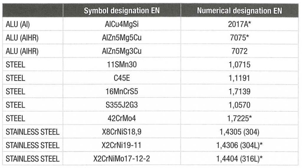
AlHR : high-strength aluminium.
* Standard material used at our production facility at BINDER magnetic in Saint-Jean de Braye.
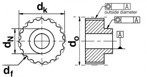
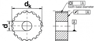
Tolerances – meshing diameters of pulleys
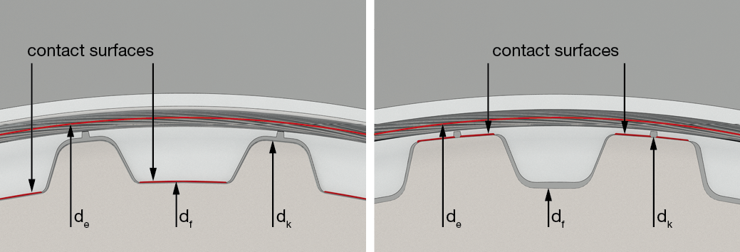
The functional meshing diameters are:
-dk (diameter of outside diameter) for pulley profiles T ≥ tolerance h8
-df (diameter at tooth base) for AT pulley profiles
Contact surfaces
| AT profile | T profile |
 |
|
For HTD pulleys the belt touches dk and df of the pulley.
For STD and CTD pulleys the contact surfaces are identical to those of the AT profile.
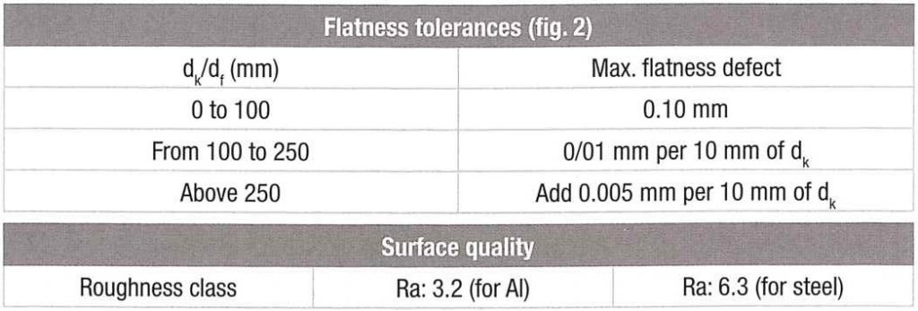
2 /General tolerances – functional dimensions of pulleys
2.1 Tolerances of pulleys:
Standard pulleys
Our standard pulleys have the following tolerances:
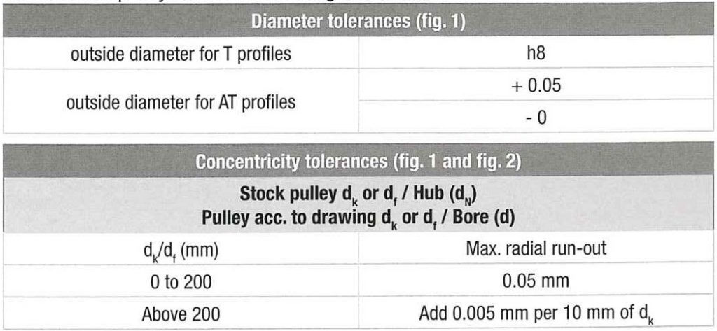
For T profile
For AT profile
– Concentricities between dk or df and bore (d) or hub (dN):
| Up to 50 mm | From 50 to 200 mm | From 200 to 400 mm |
| 0.03 | 0.05 | 0.1 |
– Bore diameter d = H7
– Keyway width: tolerance P9 or JS9 (except aluminium alloy where JS9 is not recommended).
3 / Pulley toothforms:
The standard toothform of T or AT trapezoidal profiles have functional backlash between the pulley tooth gap and the belt tooth.
For operation with a toothed rack it is necessary to provide for a specific toothform.
Certain profiles such as SFAT or ATP notably reduce the polygonal meshing effect and thus noise and vibration.
T profile

AT profile

Value of backlash on one tooth cm:
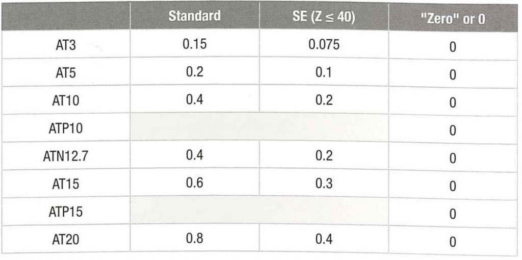
These backlash figures do not take into account either the teeth manufacturing tolerance or the belt pitch tolerance.
To approach the actual value of these backlashes in the best way it is necessary to calculate the belt elongation over its meshing.
The elongation must be considered over the length of the wrap angle on the pulley.
The actual backlash is induced by the installation tension and by the forces linked to the torque. It must be deducted from the nominal backlash.
From a certain speed and from a number of teeth in mesh zero backlash is not recommanded – Contact us for advice.
4 / Belt guiding flanges:
These serve to guide or track the belt on the pulley teeth.
The play between the belt and the flanges ranges between 2 mm and 4 mm.
For standard belts the inside width between flanges is toleranced according to the standard DIN ISO 2768-1 to take into account belt width tolerances and possible alignment errors. All the non-toleranced dimensions also follow according to the standard DIN ISO 2768-1.
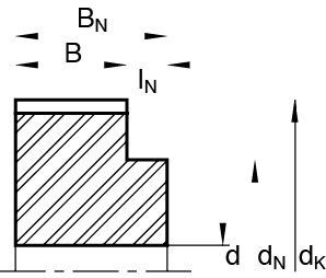
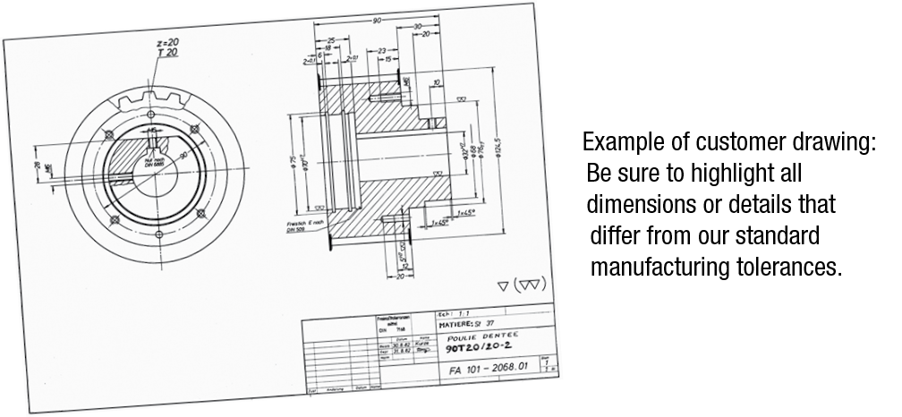
4.1 Belt flanges according to drawing:
In the case of drawings that do not contain particular specifications flanges are rolled or screwed in accordance with the profiles and the width of the belts.
Flanges that require special dimensions must be carefully dimensioned according to the sample drawing below. Our technical department will be pleased to assist you.
4.2 Standard belt flanges in stock:
These flanges conform to the defined MULCO standards thanks to European cooperation. They are made from galvanised steel and rolled or screwed.

Tolerance of flanges
The outside diameter of the guide flange is +/-0.5 mm (rolled or screwed).
Standard flanges: a large number of flanges to be rolled and screwed are produced in accordance with the MULCO standard. For screwed flanges it is advisable to consult us regarding the diameters and number of mounting screws.
| Version 0 | Version 1D | ||
 |
No flange |  |
1 flange on the hub side |
| Version 1 | Version 2 | ||
 |
1 flange on opposite the hub side |  |
2 flanges |
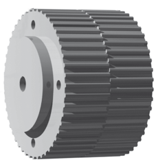
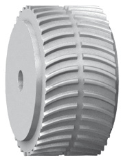
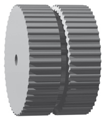
5 / Self-guiding profile pulleys:
The profiles below do not need guide flanges. It is however important to ensure that the pulleys are properly aligned.
Note: for long-length belts the alignment error is compensated in part by the elasticity of the belt.
 |
 |
 |
|
SFAT: offset teeth. Permissible alignment error < 3 mm. |
BATK: curved teeth (circle arc). Permissible alignment error < 2 mm. |
TK, ATK, HK: teeth with trapezoidal groove. Permissible alignment error < 1 mm. |
6/ Common heat and surface treatments:
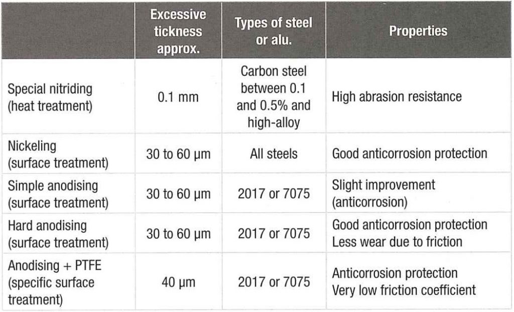
Other treatments can be performed – Contact us for further details.
7/ Designation of belts with no drawings:
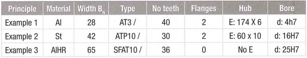
Note: Specify if a keyway is to be cut into the bore.
8/ Pulley according to drawing:
The special pulleys that we manufacture according to our customers’ drawings can contain details of specific tolerances.

Conveyor belt maintenance in industry: saving time and money
