TECHNICAL INFORMATIONS OF POWER APPLICATIONS
POWER APPLICATIONS
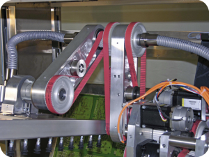
The term power application is used to define the transmission of motion from one driving pulley to one or more driven pulleys.
General design
• You are planning to produce a simple power transmission, without any specific constraints
• Or, alternately, you are looking to produce a complex transmission:
– with high dynamic load,
– requiring backlash-free angular positioning precision.
In all cases, BINDER magnetic can offer a full range of power transmission belts.
Our belts are used to produce power transmissions:
• with a low centre distance,
• for high lengths up to 22 metres,
• for the rotation of several shafts,
• with directional reversal,
• with high speed and low torque,
• with very high torque and low speed,
• with zero backlash.
It is important to be familiar with the mechanical properties of your installation and of the drive to make an optimum solution. Every belt has specific properties which can impact on the correct functioning of the assembly.
You have at your disposal a very large selection of belts:
• polyurethane base: Brecoflex®, Brecoflexmove® Synchroflex®,
CONTI® Synchrochain belts,
• polychloroprene base: CONTI® Synchroforce and CONTI® Synchrotwin belts.
They can be used in a variety of applications:
• industrial machines,
• packing machines,
• robotics,
• injection machines,
• agricultural machines…
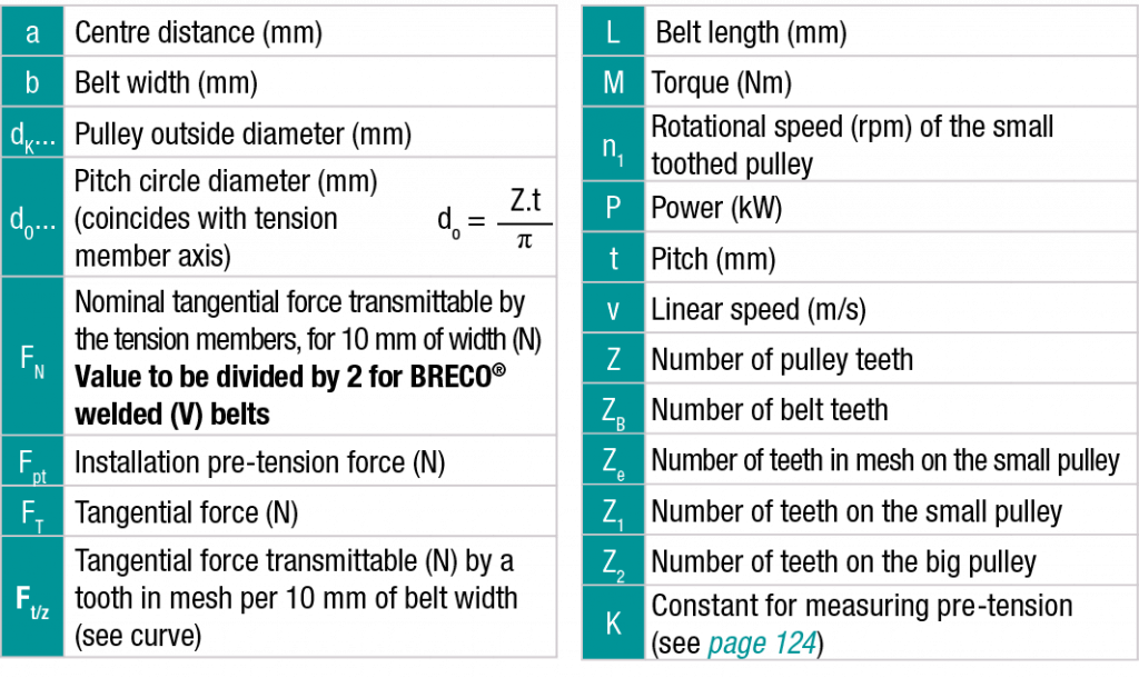
1 / Technical data
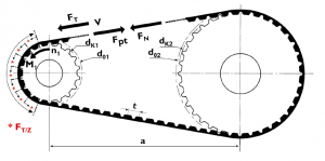
1.1 Kinematics and symbols
Ze: Number of teeth in mesh on the small pulley. For the calculation:
max. 6 for CONTI®SYNCHROFORCE CXA CXP and CONTI®SYNCHROCHAIN belts.
max. 12 for SYNCHROFLEX® and BRECOFLEX® belts.
max. 16 for SYNCHROFLEX® GEN III belts.
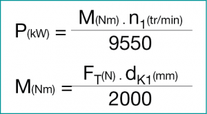
1.2 Power or torque to be transmitted
1.3 Application factors
Different factors must be taken into consideration in order to determine the type of belt chosen as follows.
Meshing factor: c1
(only applicable to CONTI®SYNCHROFORCE and CONTI®SYNCHROCHAIN belts)
|
Number of teeth in mesh |
Meshing factor c1 |
|
3 |
0,4 |
|
4 |
0,6 |
|
5 |
0,8 |
|
≥ 6 |
1,0 |
Load factor: c2
|
Connsumers |
Electric motor Mmax < 1,5 Mn Turbine motor expl 8 cyl. Cœf c2 |
Electric motor 1,5 Mn < Mmax < 2,5 Mn Turbine motor expl |
Electric motor Mmax > 2,5 Mn Mn hydraulic turbine motor |
|
Small masses to be accelerated, constant running |
1 to 1,2 |
1,3 to 1,5 |
1,6 to 1,8 |
|
Medium masses to be accelerated, constant running |
1,3 to 1,5 |
1,6 to 1,8 |
1,9 to 2,2 |
|
Medium masses to be accelerated and high shocks |
1,6 to 1,8 |
1,9 to 2,2 |
2,3 to 2,8 |
|
Larges masses to be accelerated and high shocks |
1,9 to 2,2 |
2,3 to 2,8 |
2,9 to 3,3 |
|
Large masses to be accelerated and very high shocks |
2,3 to 2,8 |
2,9 to 3,3 |
3,4 to 5 |
Step-up factor: c3
For a step-up transmission take an application factor according to the table below.
|
Step-up ratio |
Step-up factor c3 |
|
From 1 to 1,5 |
0,1 |
|
From 1,5 to 2,5 |
0,2 |
|
2,5 and more |
0,3 |
Fatigue factor: c4
(only applicable to CONTI®SYNCHROFORCE and CONTI®SYNCHROCHAIN belts)
The fatigue factor takes into account the utilisation period to guarantee an operating period.
|
Period and type of operation |
Fatigue factor c4 |
|
Daily period 10-16 h |
+0,2 |
|
Daily period > 16h |
+0,4 |
|
Additionnal contreflexure |
+0,2 |
|
Intermittent operation |
-0,2 |
Elongation factor: c5
(only applicable to CONTI®SYNCHROFORCE and CONTI®SYNCHROCHAIN belts)
The elongation factor maintains synchronisation while increasing stiffness.
|
Lenght factor c5 |
||||||
|
3M belt |
||||||
|
Belt lenght L (mm) |
< 191 |
191-260 |
261-400 |
401-600 |
> 600 |
|
|
c5 |
0,8 |
0,9 |
1,0 |
1,1 |
1,2 |
|
|
5M belt |
||||||
|
Belt lenght L (mm) |
< 441 |
441-500 |
501-800 |
801-1100 |
> 1100 |
|
|
c5 |
0,8 |
0,9 |
1,0 |
1,1 |
1,2 |
|
|
8M belt |
||||||
|
Belt lenght L (mm) |
< 640 |
640-959 |
960-1249 |
1280-1799 |
> 1799 |
|
|
c5 |
0,8 |
0,9 |
1,0 |
1,1 |
1,2 |
|
|
14M belt |
||||||
|
Belt lenght L (mm) |
< 1400 |
1400-1777 |
1778-2099 |
2100-2589 |
2590-3499 |
> 3499 |
|
c5 |
0,8 |
0,9 |
0,95 |
1,0 |
1,05 |
1,1 |
Width factor: c6
(only applicable to CONTI®SYNCHROFORCE and CONTI®SYNCHROCHAIN belts)
The values of power PN are given for a well-defined belt width. The width factor c6 must be applied to PN (reference) to obtain the transmittable power for a lower or higher belt width.
Global application factor: c0
The power to be transmitted P must be corrected based on the types of engines and consumers, on the operating conditions and on the transmission ratio if it is a step-up transmission:
– For SYNCHROFLEX® and BRECOFLEX® belts:
– For CONTI®SYNCHROFORCE and CONTI®SYNCHROCHAIN belts:
1.4 Determining the pre-tension force
The pre-tension force per span is dependent on the tangential force to be transmitted and on the number of belt teeth according to the mounting type.
|
Drive configuration |
Pre-tension force per span |
|
Two-pulley drive ZB< 60 |
Fpt = 1/3 Ft |
|
Two-pulley drive 60< ZB<150 |
Fpt = 1/2 Ft |
|
Two-pulley drive ZB>150 |
Fpt = 2/3 Ft |
|
Multiple-pulley drive L taut span=L slack span |
Fpt = Ft |
|
Multiple-pulley drive L taut span=L slack span |
Fpt > Ft |
ZB: number of belt teeth
L: belt length (in mm)
1.5 Force permissible by the tension members
In dynamics a transfer of load is effected from the slack span to the taut span, which produces a component force. The force of the taut span does not have to be higher than the nominal transmittable force.
Fbt: force in the taut span
For emergency braking the peak braking torque must be taken into account.
1.6 Determining the belt length “L” and centre distance “a”
For a simple two-pulley transmission with a 1/1 ratio
For a simple two-pulley transmission (step-down or step-up).
![]()
For a ratio of more than 5:1 contact us.
For a multiple-pulley transmission consult us with a sketch fixing the x-y coordinates of the axes and the limit of their possible variations. Our engineers will use our software to calculate the precise length of the belt.
2 / Determination method: Brecoflex® and Synchroflex®
2.1 Power or torque to be transmitted
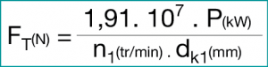
The timing belt transmits a power P (kW) or more exactly a torque M (Nm) by the teeth in mesh Ze on the small pulley of diameter dK1 (mm) turning at a speed n1 (rpm). Each tooth in mesh is capable of transmitting a maximum force of FT/Z. To define a belt, it is therefore essential to know the tangential force FT (N) which will be applied to the teeth in mesh Ze and to the tension members of the binding.
Note: For the simplicity of the calculation we liken dK to dO.
2.2Determining the belt width
Depending on the power to be transmitted the pitch is chosen in the table below, then the number of teeth in mesh Ze on the smaller pulley dk1 is determined.
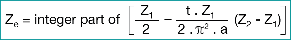
Nota: Ze can also be determined graphically.
Important – For the calculation:
- CONTI®SYNCHROCHAIN and CONTI®SYNCHROFORCE belts: maximum 6 teeth
- BRECOFLEX® and SYNCHROFLEX® belts: maximum 12 teeth
- SYNCHROFLEX® GEN III belts: maximum 16 teeth
The belt width b is determined with the formula below based on the curve sheets on the page corresponding to the chosen profile, the value FT/Z.
2.3 Quick guide to choice of profiles
|
P max (kW) |
FN* (N) for 10 mm of belt width |
Vmax (m/s) |
n rotational speed |
Belt type |
|
≤ 0,5 |
≤ 117 |
80 |
20 000 |
T2,5 |
|
≤ 5 |
≤ 380 |
80 |
20 000 |
AT3 |
|
≤ 6 |
≤ 599 |
80 |
20 000 |
AT3 GEN III |
|
≤ 15 |
≤ 700 |
60 |
10 000 |
AT5 |
|
≤ 18 |
≤ 787 |
60 |
10 000 |
AT5 GEN III |
|
≤ 70 |
≤ 1600 |
70 |
10 000 |
AT10 |
|
≤ 70 |
≤ 1600 |
70 |
10 000 |
BAT10, BATK10, SFAT10 |
|
≤ 87 |
≤ 2000 |
87 |
10 000 |
AT10 GEN III |
|
≤ 100 |
≤ 1600 |
60 |
10 000 |
ATP10 |
|
≤ 135 |
≤ 2120 |
48 |
8 000 |
SFAT15 |
|
≤140 |
≤ 2160 |
48 |
8 000 |
BATK15 |
|
≤ 150 |
≤ 2200 |
60 |
10 000 |
ATP10 GEN III |
|
≤ 160 |
≤ 2800 |
50 |
10 000 |
ATP15 GEN III |
|
≤ 200 |
≤ 2400 |
50 |
10 000 |
ATP15 |
|
≤ 200 |
≤ 2600 |
60 |
10 000 |
ATS15 |
|
≤ 200 |
≤ 2120 |
40 |
6 500 |
SFAT20 |
|
≤ 200 |
≤ 2120 |
40 |
6 500 |
AT20 |
|
≤ 250 |
≤ 2880 |
40 |
6 500 |
AT20 GEN III |
2.4 Example for determining a polyurethane belt (PU)
Let us take a power to transmit of max. 6 kW at a speed of 5600 rpm with a step-down ratio of 28/35 between a DC motor and a centrifuge. The centre distance is 150 mm ± 10 mm. What belt width and length to choose?
Determining the application factor:
Fatigue factor c2 :
Small masses to be accelerated and constant running: c2 = 1.0
Acceleration factor: c3
c3 = 0
which gives a running factor c0 : c0 = 1
- Power transmission: thus BRECOFLEX® or SYNCHROFLEX® (non-spliced belt)
- Diameter of the small pulley dk1 of 28 teeth = 43.35 mm
- Number of teeth in mesh on dk1 :
![]()
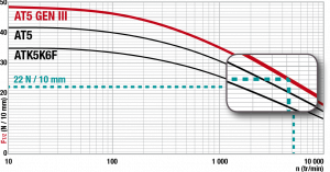
- Force transmittable by tooth: *value to be taken from the curves, in our case we have 22 N/10 mm.
- Calculation of width in relation to the teeth:

Standard width = 25
- Calculation of length:

Standard length = 455

2.5 Calculation program
The belt-pilot calculation program allows you to determine a belt and download CAO files. You can access the program on our website at:
http://www.binder-magnetic.com/pour-vous/calculez-votre-transmission

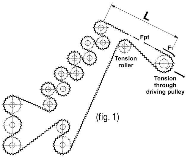
2.6 Synchronisation
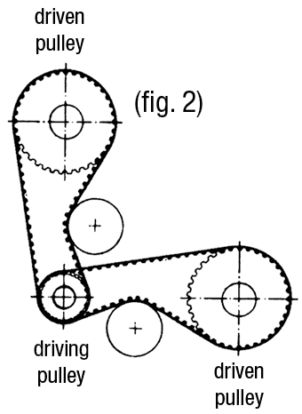
The synchronisation for multiple-pulley transmissions (fig. 1) or transmissions of a motor with several motions (fig. 2) depends on the stiffness of the belt or belts according to the application.
 |
 |
The elongation of the belt run in the acceleration or braking phase is determined using the following formula:
The stiffness constant is dependent on the elastic elongation and the nominal transmittable force.
Example: BRECOFLEX® 25AT5 timing belt

3 / Determination method: CONTI® synchrochain and CONTI® Synchroforce
3.1 Determining the belt width
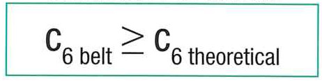
The belt width is dependent on the application factors, the meshing, the elongation and the nominal power to be transmitted. Therefore we must determine the width factor c6:
Conditions to be fulfilled:
Where
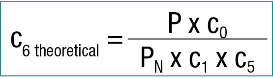
Where: P: power of installation (in kW)
PN : power in relation to table reference width (in kW)
3.2 Example of determining a polychloroprene belt
Let us take a belt transmission for sawing wood with a low ratio 38/56 starting torque.
Electric motor: P = 12 kW, Mmax = 2 x MN
Nominal rotation n1=1450 rpm.
- Driven pulley: n2=1000 rpm.
- Diameter ≤ 150 mm
- Centre distance: a ~ 300 mm
Usage condition: 16 h / day
Determining the application factor: co
Load factor: c2
Small masses to be accelerated and constant running: c2 = 1.4
Acceleration factor: c3
c3 = 0
Fatigue factor: c4
c4 = 0.2
which gives a running factor C0 :
c0 = 1.4 + 0 + 0.2 = 1,6
Selection of belt pitch which is dependent:
- on the power to be transmitted
- on the rotation of the small pulley n(k)
Choice of profile
Select the pitch and the profile according to the data in the tables representing the PN on the corresponding pages:
P(N) transmittable for belt of 20 mm width
Chosen belt: CONTI®SYNCHROFORCE CXP, HTD8
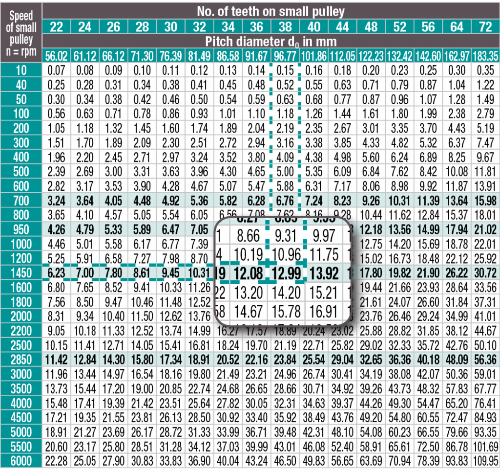
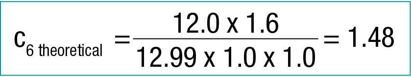
where PN = 12.99 kW
Meshing factor: c1
Number of teeth in mesh:

Ze = 18. We have more than six teeth in mesh, thus c1 = 1
Elongation factor: c5
The elongation factor is dependent on the length of the belt:
![]()
Retained belt length: 960 mm ; Z = 120
We thus have c = 1
Belt width
Conditions to be fulfilled:
Facteur de largeur c6
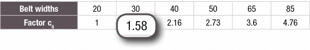
The retained factor c6 is 1.58.
PR: value of power transmittable by the selected belt.
PR = 12.99 x 1.58 = 20.53 kW
Which allows us to determine the actual application factor: c0 actual
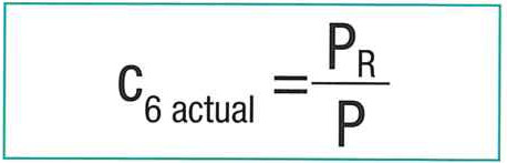
c0 actual = 20.53/12 = 1.71
3.3 Calculation program
The ContiTech calculation program allows you to determine a CONTI® SYNCHROCHAIN or CONTI® SYNCHROFORCE belt. You will find the link to access this program on our website at:
http://www.binder-magnetic.com/pour-vous/calculez-votre-transmission

4 / General tolerances
4.1 Length tolerances
|
Length tolerances in relation to centre distance |
|
|
BRECOFLEX® |
|
|
Belt lenght (mm) |
Length tolerance |
|
1000 to 1960 |
± 0,60 |
|
1960 to 3500 |
± 0,95 |
|
3500 to 4500 |
± 1,20 |
|
4500 to 6000 |
± 1,50 |
|
6000 to 10000 |
± 2,40 |
|
10000 to 22000 |
± 4,50 |
|
Length tolerances in relation to centre distance |
|
|
SYNCHROFLEX® |
|
|
Belt lenght (mm) |
Length tolerance |
|
up to 320 |
± 0,15 |
|
320 – 630 |
± 0,18 |
|
630 – 1000 |
± 0,25 |
|
1000 – 1960 |
± 0,40 |
|
1960 – 3500 |
± 0,50 |
|
3500 – 4000 |
± 0,80 |
|
4000 – 6000 |
± 1,20 |
|
Length tolerances in relation to centre distance |
|
|
CONTI® SYNCHROFORCE et CONTI® SYNCHROCHAIN |
|
|
Belt lenght (mm) |
Lengthe tolerance |
|
up to 150 |
± 0,15 |
|
151 – 255 |
± 0,20 |
|
256 – 400 |
± 0,23 |
|
401 – 560 |
± 0,25 |
|
561 – 800 |
± 0,30 |
|
801 – 1000 |
± 0,33 |
|
1001 – 1270 |
± 0,38 |
|
1271 – 1500 |
± 0,40 |
|
1501 – 1800 |
± 0,43 |
|
1801- 2000 |
± 0,45 |
|
2001 – 2250 |
± 0,48 |
|
> 2 250 |
0,05 mm per additional 500mm |
4.2 Width and thickness tolerances
|
Belt type |
Width tolerances |
Back thickness tolerances |
||
|
Up to 50 mm |
50 to 100 mm |
above 100 mm |
||
|
BRECOFLEX® – SYNCHROFLEX® |
||||
|
T2 |
± 0,3 mm |
± 0,5 mm |
± 0,5 % width |
± 0,15 mm |
|
T2,5 |
||||
|
M |
||||
|
AT3 |
||||
|
T5 |
||||
|
AT5 |
± 0,5 mm |
± 0,3 mm |
||
|
CATK5 |
||||
|
T10 |
||||
|
AT10 |
± 1 mm |
± 1 mm |
± 1 % width |
± 0,45 mm |
|
BATK10 |
||||
|
SFAT10 |
||||
|
ATP10 |
||||
|
AT15 |
||||
|
ATP15 |
||||
|
SFAT15 |
||||
|
SFAT20 |
||||
|
T20 |
||||
|
AT20 |
||||
|
CONTI® SYNCHROCHAIN |
||||
|
CTD 8M |
± 0,65 mm |
± 1,3 mm |
± 1,5 % |
± 0,30 mm |
|
CTD 14M |
± 1 mm |
± 2 mm |
± 2 % |
±0,45 mm |
|
CONTI® SYNCHROFORCE HTD |
|||
|
Width b (mm) |
Width tolerance for a length L in mm |
||
|
< 880 (mm) |
from 881 to 1760 (mm) |
>1760 (mm) |
|
|
≤ 9 |
+ 0,4 |
+ 0,4 |
|
|
– 0,8 |
– 0,8 |
||
|
10 – 40 |
+ 0,8 |
+ 0,8 |
+ 0,8 |
|
– 0,8 |
– 1,2 |
– 1,2 |
|
|
41 – 50 |
+0,8 |
+ 1,2 |
+ 1,2 |
|
– 1,2 |
– 1,2 |
– 1,5 |
|
|
51 – 85 |
+ 1,2 |
+ 1,5 |
+ 1,5 |
|
– 1,2 |
– 1,5 |
– 2,0 |
|
|
86 – 170 |
+ 1,5 |
+ 1,5 |
+ 2 |
|
– 1,5 |
– 2,0 |
– 2,0 |
|
|
> 170 |
+ 4,8 |
+ 4,8 |
|
|
– 4,8 |
– 4,8 |
||
|
CONTI® SYNCHROFORCE HTD |
||||
|
Type |
HTD5M |
HTD 8M |
STD 8M |
HTD 14M |
|
Pitch in mm |
5 |
8 |
8 |
14 |
|
Thickness tolerance |
± 0,25 |
±0,40 |
± 0,40 |
± 0,60 |

Timing belts or chains: 5 reasons to switch to timing belts
