TECHNICAL EXPLANATIONS FOR HOLDING MAGNETS
ELECTROMAGNETIC HOLDING MAGNETS
Our products conform to the production standard DIN VDE0580 and are RoHS-compliant.
TYPES OF HOLDING MAGNET
Electromagnetic holding magnets:
The ferromagnetic part is held in place on the holding magnet’s attraction surface when power is supplied to the coil. When the holding magnet is not powered, the electromagnetic force is removed and the ferromagnetic part is released.
Electro-permanent holding magnets with integrated permanent magnet:
A ferromagnetic part is held in place on the holding magnet thanks to a permanent magnet that is integrated in the holding magnet and continues to hold the part when no current is applied.
The magnetic field created when the coil is powered is opposite to that of the permanent magnet and cancels out its action. This releases the ferromagnetic part located on the attraction surface.
The force induced by the permanent magnet is present again when the supply voltage is interrupted, thus attracting the ferromagnetic part.
BASIC ELEMENTS
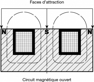
Magnetic circuit:
The attraction surface of the holding magnet consists of two poles (North = N and South = S).
The flux flows from one pole of the holding magnet to the other and passes via the ferromagnetic part that is to be held.
This flux then generates an electromagnetic force that holds the part at the poles of the holding magnet.
 |
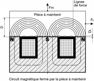 |
Holding force (Fm):
Holding force (in N) of the holding magnet, under optimum conditions of use, at the ferromagnetic part when it comes into contact with it.
This force is perpendicular to the attraction surface of the holding magnet. It is specified in the catalogue and corresponds to the situation in which the poles of the holding magnet are fully covered by the part to be held when in contact with it.
This holding force will fall when the ambient temperature rises above 35 °C. In effect, when the ambient temperature increases, so too does the resistance of the coil, thus inducing a fall in current and magnetic flow, and consequently also a loss of force.
Sliding force (Fg):
Maximum lateral force (in N) permitted at the holding magnet before the part to be held slides tangentially on the attraction surface.
This force depends on the surface state of the part to be held and is approximately 20% to 35% of the holding force.
Residual force (Fr):
Residual force (in N) through which the holding magnet holds the ferromagnetic part after removal of the magnetic field associated with the coil or the permanent magnet.
Its value is at least 15% of the holding force and depends on the part (size, roughness, material, etc.). It may be as much as approximately 30%.
VOLTAGE, CURRENT AND POWER
Nominal voltage (Un):
The nominal voltage defined for the holding magnet (in V).
The tolerance for this voltage for the holding magnets in this catalogue is between +5% and -10%.
Nominal current (In for DC current):
Intensity of the current (in A) consumed by the coil at a temperature of 20 °C and at the nominal voltage (Un). The nominal current is calculated by dividing the consumed power (Pn in W) by the nominal voltage (Un in V). To determine the current consumed by the solenoid at 20 °C, use the following formulae:
![]()
P = power (in W).
I = current (in A) – Variable as a function of the temperature and the power supply.
U = min. voltage (in V) – Variable as a function of the power supply.
R = resistance (en Ω) – Variable as a function of the temperature.
Nominal consumed power (Pn):
Capacity (in W) of the coil at the nominal voltage and at a coil temperature of 20 °C. It is calculated by multiplying the nominal voltage (Un in V) by the nominal current (In in A). P = UI (see above)
Electrical resistance (in Ω):
Electrical resistance of the coil (in Ω) – Manufacturing tolerance: ±10%
Duty factor (DF):
The duty factor (in %) corresponds to a ratio between the period during which the solenoid is active (Du) and the reference period (Dt).
Du: corresponds to the effective total period during which the solenoid is powered during a reference period (Dt).
Dt: corresponds to the reference period, which is defined by our factory for each unit (between 2 and 5 minutes).
Calculation of the duty factor:
![]()
Example: Du = 2 min actually powered during a period (Dt) of 5 min for the unit / Dt = 5 min. I.e. DF = 2/5 x 100 = 40%
Insulation class of the coil:
The insulating varnish of the coil’s copper wire permits electrical insulation between the coil’s turns.
The thermal insulation class, which is associated with this varnish, indicates the maximum permissible temperature of the coil as it heats up.
Choosing the right insulation class allows the solenoid to function correctly under the voltage, duty factor and ambient temperature conditions defined for the unit.
|
Insulation class |
Limit temperature (°C) V21 |
Maximum heating at an ambient temperature of 35 °C |
| Y | 90 | 50 |
| A | 105 | 65 |
| E | 120 | 80 |
| B | 130 | 90 |
| F | 155 | 115 |
| H | 180 | 140 |
| C | 200 | >200 |
Ambient operating temperature:
The ambient temperature should be between -5 °C and +35 °C.
Maximum ambient operating temperature:
When the supply voltage is at the upper maximum limit of tolerance, the maximum ambient temperature is 55 °C For higher temperatures, please consult us.
Wiring diagram:
There are many different possibilities. However, we recommend that you use a diode and resistor in parallel. In effect, the interruption of the power supply to the coil causes a voltage peak at the control switch, which in turn generates an electric arc. This can result in the deterioration of various components. This phenomenon is associated with the induction coil. By wiring as indicated below, it is possible to greatly restrict this arc.

EFFICIENCY CRITERIA
Magnetic flux (B in Tesla):
Holding magnets produce a magnetic field between the North and South poles on the holding surface. When the ferromagnetic part is moved towards the magnetic circuit, the field lines in the circuit move closer together. The density of the field lines across a surface is the flux density, also known as magnetic induction.
Important: the most important mechanical criteria that need to be taken into account in order to optimize the strength of a holding magnet include:
– the air gaps that are present,
– the suitability of the thickness of the part to be held,
– the quality of the ferromagnetic steel that is to be held,
– the proportion of the surface area that is actually in contact.
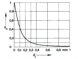
Air gap (∆ L):
Mean distance between the holding magnet’s attraction surface and the surface of the ferromagnetic part that is to be held. Many different factors may affect this distance.
For example, it is necessary to take account of the points below in order to estimate the actual effective air gap:
– any surface treatment of the part to be held, This could take the form of paint
or corrosion-proofing, galvanization, nickel-plating, etc. It could also be a film of
grease or dust, etc.
Note: all the holding magnets presented in this catalogue have been electrogalvanized to protect them against corrosion. The measurements of holding force have been performed with standard corrosion-proofing treatment of the holding magnet of approximately 10 microns.
– roughness of the part to be held greater than Ra 0.8. Above a roughness of Ra 0.8, it will be necessary to take account of an additional air gap of:
-
as of Ra 1.6: ∆ L = 0.05 mm
-
between Ra 6.3 and 12.5: ∆ L = 0.1 mm
Note: any significant mechanical impact at the holding magnet’s holding surface may cause unevenness and therefore also an air gap.
– planarity of the part to be held greater than 0.01 mm. Beyond this, the planarity error must be added to the air gap.
In conclusion: to optimize the strength of the holding magnet, it is necessary to attempt to reduce the air gap to a minimum.
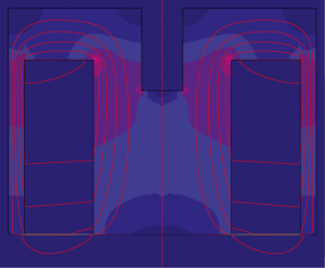
Thickness of the part to be held:
It is the thickness of the part to be held that truly defines the holding force (Fm). In effect, the thicker the part is, the greater the number of magnetic field lines passing through the part. If the part to be held is too thin then it will not be able to accommodate all the available field lines and will become saturated. The force will then be inadequate.
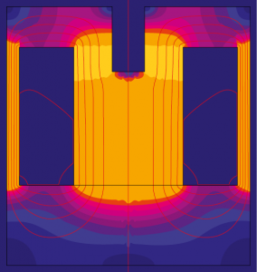
Behaviour of the magnetic field and the field lines as a function of the thickness of the part to be held:
 |
|
Part of thickness 0.2 mm |
 |
|
Part of thickness 10 mm |
Material of the part to be held:
For a field intensity determined by the permanent magnet or the coil of the holding magnet, the induction is a function of the material of the part to be held.
The magnetic permeability of the material to be held is important and also determines the actual holding force (Fm).
The proportion of “iron” in the steel alloy from which the part is made is therefore important for determining the force (Fm).
The forces indicated in the documentation are given for steel 1.0345 (A37)
Nota :
1 – A mild steel, with very little carbon, will have a good level of magnetic permeability but very little mechanical strength.
2 – Certain heat treatments, such as quenching, can reduce the material’s magnetic permeability.
Proportion of the surface area actually in contact:
The magnetic field traverses the holding magnet from one pole to the other. If a ferrous part that is in contact with the holding magnet does not completely cover the entire surface of the two poles of the holding magnet then the magnetic field is reduced by an amount proportional to the surface area that is actually covered. The force then also falls approximately in proportion to this reduction. Take account of the proportional surface area of the pole that has the lesser coverage (often the external pole).
This phenomenon is frequently observed, in particular if the part to be held:
– has drill holes,
– is not centred on the holding magnet and a part of the external pole is not covered,
– has undulations (and is therefore not flat).
The back plates presented in this documentation are manufactured from a magnetically optimized steel (material 1.0345 + annealing). They have an Fe/Zn 10 corrosion-proofing treatment, planarity of less than or equal to 0.01 mm (surface grinding has been performed), a diameter greater than the diameter of the holding magnet (to be sure of covering the entire surface area of the holding magnet) and a thickness suitable for the diameter and size of the holding magnet.

Timing belts or chains: 5 reasons to switch to timing belts
